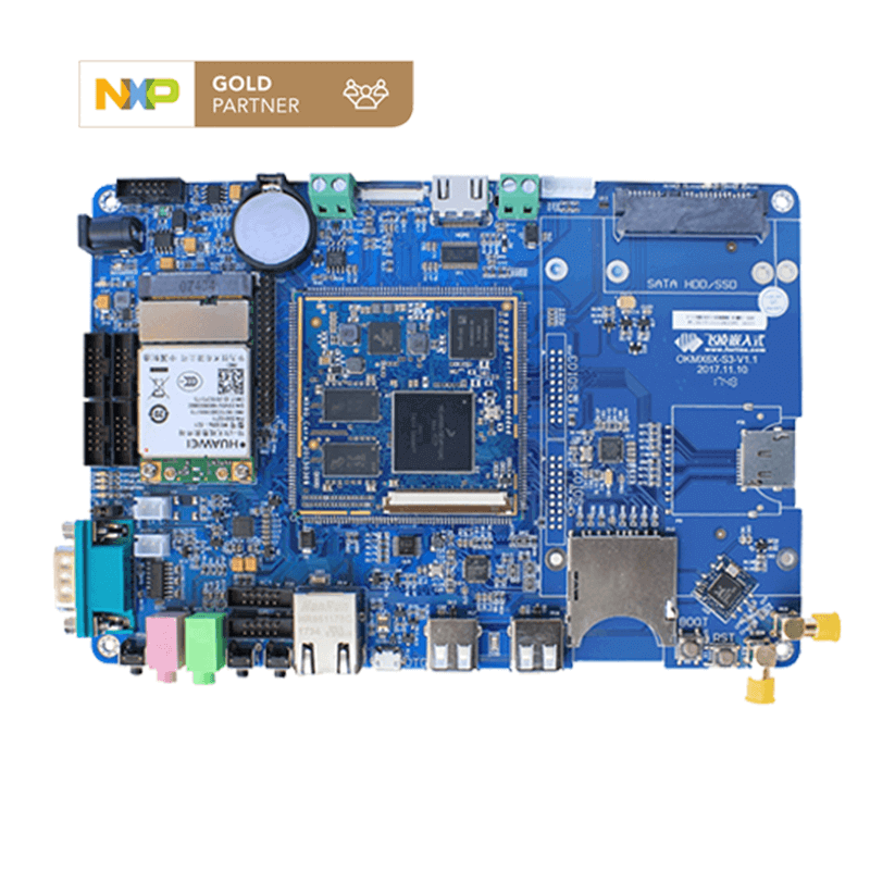
The iMX6 Development Board Base Board Interface Description
imx6 board Base plate description:
iMX6 base plate power requirements
The DC 12V power supply introduced by the DC-005 socket or DC128-5.0 green terminal is divided into three lanes after an anti-reverse diode. One Lane through the EUP3485 buck to 5V, the other lane through the Si4435DY field effect tube to the SATA hard drive 12V power supply end, and the last lane to the LVDS LCD socket. EUP3485 is a wide range synchronous buck regulator, only when the base plate has not been mounted SATA hard drive and LVDS LCD screen, 12V power supply deviation can be appropriately relaxed, otherwise it is necessary to follow the 12V ± 5% power supply.
The iMX6 development platform also consumes different power in different states. The 12V power supply output current is about 350mA in a stable state, about 500mA when 1080P video is played, and about 100mA after hibernation, after install Forlinx 7’’ Screen and start Android 4.4 system. In practice, it is recommended to select a 12V switching power adapter with an output current of not less than 2A, and replace the higher power adapter if you need to mount high-power peripherals such as a 3.5-inch hard drive.
RS-485
The interface uses ADI's all-in-one magnetically coupled isolation RS-422/485 transceiver chip ADM2587E, which requires no DC/DC isolation module and has a small footprint. The chip is fixedly configured in 485 mode and is controlled by the 197th foot of the core board (network name: DISP0_PWR_EN) by default. If the control foot needs to be diverted for other purposes in product development, the "0 delay" automatic send and receive control circuit can be enabled. The circuit is compatible on the base plate PCB and is vacant by default. For greater protection, the back of the PCB has a 7.6×5 patch three-end gas discharge tube and a TVS pad in the SMB package, which the user can add on their own.
CAN
Similar to the RS-485 interface, the CAN interface base plate also reserves a TVS pad in the SMB package for users in need to add themselves.
SD/MMC card holder
Support for SD, SDHC, SDXC (UHS-I) and MMC cards. When the SDXC card is rated UHS-II or higher, it is downgraded to UHS-I use. The reason is that starting with UHS-II, new data feet have been added (analog USB 3.0 is different from the past).
Mount lithium-ion/polymer batteries
The iMX6 development board has two separate lithium battery charge and discharge management circuits installed on the base plate that can mount two lithium-ion/polymer batteries (Lithium-ion) and do not support lithium phosphate (LiFePO4) or similar batteries. The CPU can independently monitor the fault and charging status of each battery, while the voltage is detected together by the "merger" of resistance. There is no protection on the interfaces of the two lithium batteries, and users should exercise greater care when wiring, in addition to choosing batteries with their own protective panels. It is best to use the same type of two batteries in the same batch, in the same voltage premise access.
Remember: Any object with a high energy density is in danger of exploding. If you're not technically sure, don't touch the lithium battery!
RTC battery
Factory-shipped RTC battery is a corded CR2032, after running out of power, with the same type of battery replacement can be, replace should pay attention to plug specifications and positive and negative polarity do not get wrong.
WiFi/Bluetooth
The WiFi Bluetooth 2-in-1 module is on the back of the PCB and is available in RealTek RTL8723AS Combo Module, IEEE 802.11 b/g/n 2.4GHz 1T1R WiFi with Bluetooth v2.1 and EDR/Bluetooth 3.0/3.0 plus HS/4.0. Antenna interface in the upper right corner of the front of the PCB, pay attention to plug in the antenna do not operate savagely.
SATA hard drive interface
The 3.5-inch hard drive requires both 12V and 5V power supplies to work, with 12V power coming from the 12V power adapter, so when the base plate is battery-powered, the 3.5-inch hard drive does not work due to a missing 12V voltage.
Most consumer 2.5-inch hard drives, whether mechanical or SSDs, do not require a 12V power supply and can operate on batteries. Some high-end SSDs, although the appearance is also 2.5 inches, but the need for 12V power supply, the specific need to consult the relevant data sheet.
Touchpad interface
The touchpad connector is located between the HDMI-A socket and the SATA socket and is reserved for the contactpad, which Isaac does not provide.
Digital camera interface
The default OV5640 camera, 5M pixels.
Universal serial port
UART2: Three-wire serial port with serial 2 socket and RS-485 interface chip (ADM2587E).
If a 3.3V-level serial device needs to be connected with a serial port 2 socket, at least the jumper resistor R148 connected to the 485 chip needs to be removed, otherwise the output of the ADM2587E will conflict with the output signal of the serial device.
If you need to connect the serial device with the serial port 2 socket to the RS-232 level, you need to add the MAX3232 or compatible chip, and modify the jumper resistance, the RS-232 level into the serial 2 socket, if protection is required, you can also add the SMB package TVS, and finally at least remove the R148, so as not to conflict with the output of the MAX3232 output.
UART3: five-wire serial port, connected to the end of the board serial port 3 socket, the default is 3.3V level. If you need to connect RS-232 level serial device with serial port 3 socket, the modification method is similar to UART2 and will not be repeated.
UART4: Three-wire serial port, with serial 4 socket and GPS module (VK1613). If a serial device with a serial level of 3.3V or RS-232 level needs to be connected with a serial port 4 socket, the modification method is similar to UART2 and will not be repeated.
GPS
Default VK1613 module, SIRF3 scheme, external magnetic suction active antenna. A pad with a shield is reserved on the PCB, but Forlinx does not currently provide a shield. Users who need to strengthen the shielding effect can manufacture and weld the shield on their own.
Infrared remote control
The infrared remote control itself need not be repeated, but when debugging the infrared remote control function, it is sometimes necessary to verify that the remote control is working properly. But the human eye can not see infrared light (can see is not called red "outside" light). At this time can turn on the phone's camera function, the remote control to the phone camera and press the button of the remote control, if you can see the remote control head white light on the phone screen, the remote control is working normally.
LVDS
Supports 2 LVDS output channels, each containing 1 pair of clock lines and 4 pairs of data lines. The standard single LVDS interface and dual LVDS interface are reserved on the base plate, and the supply voltage to the LCD screen is 3.3V, 5V and 12V optional. The base plate also reserves a standard backlight interface that supports switch control, but does not support analog voltage dimming, and can only be pre-set by resistance and cannot be dynamically adjusted.
Mini PCI Express
Reserve the standard Mini PCIE slot, support for half-height and full-height modules, with the SIM card slot on the back.
Audio
The headphone and horn outputs are stereo and the microphone input is mono. The two white XH2.54-2P sockets are the class D amplifier output within the audio chip WM8962, with an output of 1W when connected to an 8o horn and 2W when connected to a 4o horn. Note: The power of the horn comes from class D amplifiers, not traditional analog amplifiers. Each socket is connected to a horn, must not share the horn line, also can not be the horn to the ground line. If a larger amplifier needs to be external, the signal can only be obtained from the headphone socket and not from the horn connector.
Debug the serial port
UART1 is a debug serial port. Considering that computers now have very few serial ports, the bottom plate is added USB to 3.3V serial chip, through the Micro USB cable to connect the computer. The power supply to the conversion chip is provided by the computer and does not depend on the base plate. Just connect the data cable, regardless of Whether the i.MX6 is powered on or not, the conversion circuit will work correctly. Avoid missing debug information due to computer system identification of chips and installation of drivers.
In order to ensure the smooth commissioning work, USB re-serial chip is the industry-renowned FT232RQ, this chip is known for its stability, the quality is much higher than the market common cheap chip.
In addition, UART1 is directly drawn out by a 3P pin with a 2.54mm pitch in case of need.
USB OTG interface
USB OTG is an abbreviation for USB On-The-Go. Simply put, when a USB OTG-enabled device (in the case of the iMX6 board) is connected to a USB master (in the case of a computer), i.MX6 recognizes that it is connected to the main device and then communicates with the computer from the device, without powering the USB-OTG port; When the MX6 is connected to the USB drive, the i.MX6 recognizes that it is connected from the device, and then communicates with the USB drive as the primary device, and powers up the USB-OTG port to power the USB disk.