Forlinx RK3588 SoM Circuit Problems: MaskRom Mode Entry Causes and Solutions
Problems Description:
When using the Forlinx RK3588 SoM and a homemade carrier board, the system enters MaskRom mode as soon as it's powered on. The difference between the Forlinx carrier board and the homemade carrier board lies in the value of the ground capacitors in Figure 1, where one is 10uF and the other is 100nF.
Solutions:
The MaskRom mode of OK3588-C can only be pulled low to GND by the BOOT _ SARADC _ IN0 when the CPU starts to detect.
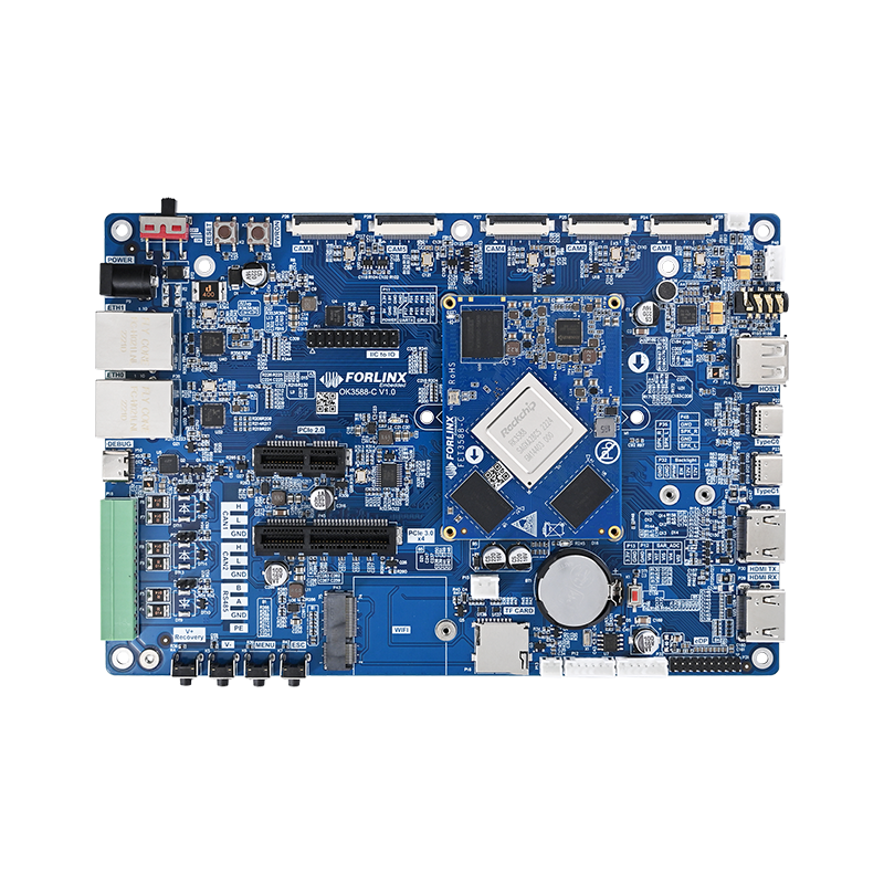
The OK3588-C development board enters MaskRom mode by tapping the BOOT _ SARADC _ IN0 to GND. As shown in the figure 1: This part of the circuit has a 100 nF capacitor C3 to ground. If this capacitor is replaced with a larger one, such as a 10 uF capacitor, it will cause the development board to enter MaskRom mode as soon as it is powered on.
Figure 1
This is because capacitors have the property of blocking direct current while allowing alternating current to pass, and they also exhibit charging and discharging characteristics. When the power is turned on, the capacitor charges instantaneously, and the voltage across the capacitor cannot change abruptly. Initially, the voltage across the capacitor is zero while it charges, and then it rises exponentially according to a certain pattern until it reaches a steady state. Entering a steady state is equivalent to an open circuit. The charging process is shown in Figure 2.
Figure 2
The charging and discharging time of a capacitor increases as its capacitance value increases. A 10uF capacitor has a longer charging time, and it enters a steady state slowly. When the OK3588-C SoM starts up, if the CPU detects that the signal level of the BOOT_SARADC_IN0 pin is within the low voltage range, it assumes that this pin is pulled to GND, thus entering MaskRom mode. The solution is to remove the 10uF capacitor or replace it with a 100nF capacitor.


