Introduction to SPI Communication in the TI AM62x Processor
The Serial Peripheral Interface (SPI) communication bus is widely used for its high speed, full-duplex, synchronous characteristics. With only four lines required for data transmission, it effectively saves the number of chip pins, while also bringing spatial optimization and convenience to PCB layout. Because of its simplicity and ease of use, more and more chips are now choosing to integrate the SPI communication protocol.
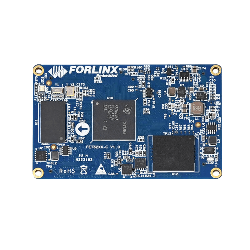
The TI AM62x processor, a new generation MPU product in the TI Sitara™ product line, features up to 4 x SPI interfaces and 1 x OSPI interface (also known as QSPI). This rich SPI interface configuration allows simultaneous communication with multiple devices, significantly enhancing system scalability and flexibility.
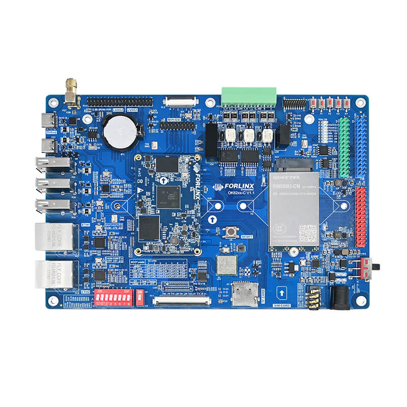
OK6254-C development board launched by Forlinx Embedded is equipped with the AM62x processor, and its NOR Flash memory is operated through the OSPI bus connection with the processor to fulfill its functionality.
SPI Workflow and Timing
We first need to look at how the SPI works – typically the SPI is connected to an external device via 4 pins:
- MISO: Master Device Input/Slave Device Output Pin
This pin sends data in slave mode and receives data in master mode; - MOSI: Master Device Output/Slave Device Input Pin
This pin sends data in master mode and receives data in slave mode; - CLK: serial port clock
As the output of the master device and the input of the slave device; - NSS: Select from Slave Device
This is an optional pin to select the slave device.
SPI Workflow:
- The host first pulls down the NSS signal to ensure that it starts to receive data;
- When the receiving end detects the edge signal of the clock, it will immediately read the signal on the data line, thus obtaining a bit of data;
- Since the clock is sent with the data, it is not important to specify the transmission speed of the data, although the device will have the highest speed at which it can operate;
- When the master sends to the slave, the master generates the corresponding clock signal, and then the data will be sent to the slave one by one from the MOSI signal line;
- When the host receives data from the slave and requires the slave to transmit data back, the host will continuously generate a predetermined clock signal, and the slave will then send data through the MISO line.
The SPI operating timing diagram is shown below:
Features of SPI Bus in AM62x Processor
TI has designed the SPI MISO and MOSI as d0 and d1 in the AM62x chip. The setting “ti,pindir-d0-out-d1-in=” in the device tree determines which one is set as input and which one is set as output.
The default attribute value is 0, i.e., d0 is the input and d1 is the output;
When the attribute value is 1, d0 is an output and d1 is an input.
SPI Application of TI's AM62x
1. Menuconfig Configuration:
Check this item and the SPI driver will be compiled into the kernel.
makemenuconfiDeviceDrivers ->SPIsupport ->Usermode SPI device driver support(Note: SPI driver compilation is in the Folinx Embedded OK6254-C single board computer.)
2. Device tree Configuration:
(1) Select the SPI to be used, here we use spi0, and the node is & main _ spi0;
(2) Multiplex the pins used by this node to the appropriate function.
(3) Describe the attributes of the node. See the notes for the functions of specific configuration items.
3. Compile and Burn:
Enter the following command in the source path:
Compilation is successful if no error is reported.
Put the OK6254-C.dtb file in image under the source path into the /boot directory of the development board and reboot the board.
4. SPI Test:
Short circuit spi0 _ D0 and spi0 _ D1
After rebooting the development board, you see two more spidev devices in the /dev directory.
Use our test program
The following printing information indicates success.
spimode: 0
bitsper word: 8
maxspeed: 42000 Hz (42 KHz)
FFFF FF FF FF FF
4000 00 00 00 95
FFFF FF FF FF FF
FFFF FF FF FF FF
FFFF FF FF FF FF
DEAD BE EF BA AD
F00D
Summary:
TI AM62x processor offers ample SPI resources, serving as a versatile bus for numerous devices, facilitating access to a wide array of peripherals. Hence, for applications demanding robust SPI capabilities, the TI AM62x stands out as an excellent choice for master control.