3.6Mbps Stable Bandwidth: Analysis of the 8-channel CAN-FD Technical Solution for the Forlinx Embedded T536 SoM
In high-tech fields such as new energy vehicle battery management systems, industrial automation control, and smart grids, the demand for real-time collection of battery module data is growing exponentially with the large-scale development of battery packs. Taking new energy vehicles as an example, modern large-scale power battery packs generally integrate hundreds to thousands of battery cells. Each cell requires continuous monitoring of core parameters such as voltage, temperature, and state of charge (SOC), resulting in an exponential increase in data throughput.
Although the Controller Area Network (CAN) bus has long been the mainstream protocol for battery data transmission due to its excellent real-time performance, anti-interference ability, and transmission reliability, in the face of ultra-large-scale battery pack monitoring scenarios, the limited number of CAN interfaces of traditional processors has gradually become a bottleneck restricting system performance.
1. T536-C SoM with 8-channel CAN-FD Support
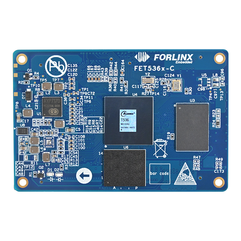
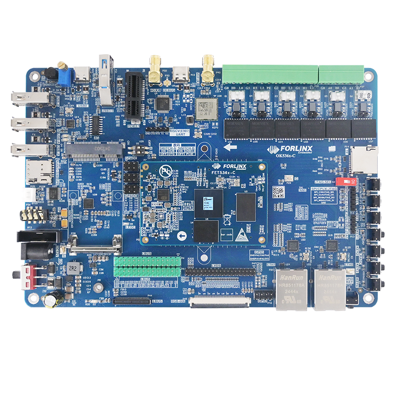
Against this backdrop, the FET536-C SoM developed by Forlinx Embedded based on the Allwinner T536 processor is an ideal choice for the main controller. The FET536-C SoM natively supports 4 x CAN-FD interfaces and can be expanded via 4 SPI-to-CAN-FD interfaces, directly meeting the requirement for 8-channel CAN-FD parallel data collection!
Equipped with a 4-core A55 architecture CPU with a main frequency of 1.6 GHz, it has the ability of thread-level load balancing. When facing a large amount of data generated by 8-channel CAN-FD parallel reception, the high-performance CPU can reasonably allocate tasks such as data processing and interrupt response to different cores, avoiding over-loading of a single core.
2. Multi-threaded Architecture for an Efficient Data Link
Forlinx Embedded has designed an 8x CAN-FD technology demonstration solution based on the FET536-C SoM. Its architecture is divided into three levels: the lower computer, the middle computer, and the upper computer, which work together to achieve 8 x CAN-FD parallel processing. The following is the system framework diagram and a detailed explanation of the functions of each layer:
01 Lower Computer
The lower computer is the part of the system that directly contacts the battery and is usually referred to as an actuator or a sensor. The lower computer is responsible for collecting real-time battery data, such as battery power and internal resistance, and uploading this data to the middle computer. In this demonstration solution, the main functions of the lower computer include:
- Data collection: Collect 8-channel CAN-FD data.
- Simulated button operation: Use buttons to simulate the battery capacity. Each press of the button will cyclically increase the battery capacity, and the battery capacity information will be sent to the middle computer.
02 Middle Computer
The middle computer plays a bridging role in the system. As the data and communication hub, on the one hand, it obtains the underlying battery system data from the lower computer; on the other hand, it is responsible for reporting the data to the upper computer. The main functions of the middle computer include:
- Data reception: Obtain the underlying battery capacity data and the number of frames sent per unit time of the 8-channel CAN-FD channels from the lower computer. Calculate the bandwidth data of each channel based on the number of frames and update the shared memory.
- Data upload: Send the calculated bandwidth data and battery capacity data to the upper computer via Socket for analysis and interface display.
03 Upper Computer
The upper computer is the control device at the top of the entire test system. The main functions of the upper computer include:
- Data receiving: Connect to the middle computer via Socket and receive bandwidth and battery capacity data from the middle computer.
- Visual interface display: The interface shows the bandwidth change curve and real-time battery capacity for users to analyze.
3. Four Optimization Strategies to Improve Performance Limits
01 Channel Performance Tuning
- Buffer expansion: Expand the receiving buffer to reduce the packet loss rate under high load.
- CPU affinity binding: Avoid resource contention and achieve load balancing.
02 Parallel Processing Optimization
- Non-blocking I/O and batch reading: Avoid thread blocking and cyclically read all frames to be processed.
- Atomic operations instead of locks: Obtain the frame count of each channel and eliminate the performance bottleneck caused by lock competition.
03 Communication Protocol Enhancement
- CAN-FD protocol adaptation: Enable the FD mode (data segment at 4Mbps), and the data-carrying capacity of extended frames and single frames is increased to 64 bytes.
- Reliable TCP transmission: Prevent the process from crashing due to client disconnection and support the disconnection reconnection mechanism.
4. Impressive Results Display
01 Verification of Core Indicators
| Test Items | Native CAN Channels (Channels 1-4) | SPI-to-CAN Channels (Channels 5-8) |
|---|---|---|
| Bandwidth Utilization | ≥85% | ≥70% |
| Maximum Receiving Rate | 5000 frame/s | 4200 frame/s |
| Continuous operation stability | 7×24-hour fault-free | Data loss rate< 0.01% |
| Real-time test | When the corresponding button is pressed in the lower-computer program, the display of the upper-computer program changes immediately. | |
02 Real-time Monitoring Effect
As shown in the video: The real-time bandwidth monitoring curves of the 8-channel CAN-FD channels indicate that the native channels are stable at 3.2-3.6 Mbps, and the extended channels are stable at 2.9 Mbps. When the lower-computer buttons are used to simulate the battery capacity gradually increasing, being set to 0, and then increasing again, the middle computer quickly responds, receives, and uploads the data to the upper computer. The upper-computer interface can immediately display the corresponding changes.
Parallel Processing of 8 x CAN-FD Channels Based on FET536-C SoM
03 Application Value
- New Energy Scenarios: It supports real-time monitoring of battery packs with hundreds of cells, with a data delay of < 10 ms.
- Industrial Automation: The 8-channel parallel data acquisition meets the requirements of multi-device collaborative control, significantly improving the system response efficiency.
- Technological Forward-looking: It provides a high-bandwidth communication paradigm for the next-generation in-vehicle ECUs and smart grid edge computing.
05 Summary
The 8 x CAN-FD technology demonstration solution based on Forlinx Embedded's T536 SoM successfully solves the problem of high-bandwidth receiving of eight CAN-FD channels through multi-core architecture optimization, in-depth protocol stack tuning, and parallel processing technology. In the wave of digital transformation in the field of new energy and industry, this technology provides a reusable engineering solution for real-time acquisition of massive data, and promotes embedded systems to move towards high concurrency and low latency.