How To Use SPI Bus Of AM625x?
What is SPI?
SPI is a high-speed, full-duplex, synchronous communication bus. It only occupies four wires on the pins of chip, which saves the pins of chip, and saves space for PCB layout. Because of this easy-to-use feature, more and more chips now integrate this communication protocol.
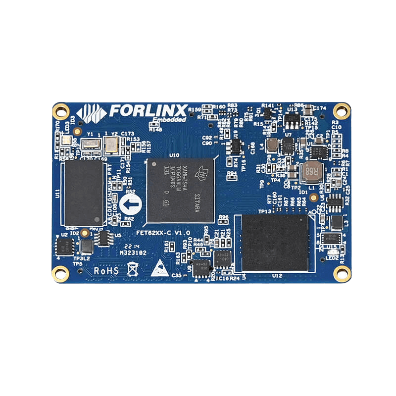
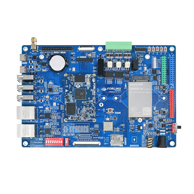
TI AM62x has 4 channels SPI and 1 channel QSPI. It can connect multiple devices at the same time. The NOR Flash of Forlinx OK6254-C development board is connected to OSPI (QSPI) bus.
How does SPI work?
Usually SPI is connected to external devices through 4 pins:
MISO:
Master input/slave output pin. This pin transmits data in slave mode and receives data in master mode
MOSI:
Master output/slave input pin. This pin transmits data in master mode and receives data in slave mode
CLK:
serial port clock, used as output of master device, input of slave device
NSS:
Select slave device. This is an optional pin used to select slave device.
SPI workflow:
Host first pulls down NSS signal to ensure that it starts to receive data;
When receiving end detects the edge signal of clock, it will immediately read the signal on data line. Thus obtaining 1bit;
Since clock is sent with data, it doesn't matter how fast the data is specified, although device will have the highest speed it can run;
Master sends data to slave: master generates a corresponding clock signal, and then the data is sent to slave from MOSI signal line 1bit by 1bit;
Master receives slave data: If slave needs to send data back to master, master will continue to generate a predetermined number of clock signals, and slave will send the data by MISO signal line.
What are the characteristics of SPI bus in AM625x?
In AM625x, TI designs MISO and MOSI of SPI as d0 and d1, which one is used as input or output, determined by ti, pindir-d0-out-d1-in=set in device tree.
The default value of this property is 0, that is, d0 is input and d1 is output. When it is 1, d0 is output and d1 is input.
AM62x SPI application
1. menuconfig configuration
If this item is selected, SPI driver will be compiled into kernel.
makemenuconfi
DeviceDrivers ->
SPIsupport ->
Usermode SPI device driver support
Note: In Forlinx OK6254-C development board, SPI driver has been compiled into kernel.
2. How to configure device tree
2.1. Select the spi to be used, here we use spi0, and the node is &main_spi0
2.2. Multiplex the pins used by this node to the corresponding function.
2.3. Describe the properties of the node, see the notes for functions of specific configuration items.
&main_spi0 {
	status "okay";
	pinctrl-names "default";
	pinctrl-g=<&spi0_pins_default>;  /* Description of pin control node */
	ti,spi-num-cs=;  /* Description of the number of chip selects */
	ti,pindir-d0-out-d1-in =;  /* Description of which is input and which is output */
	/* Description of the sub-node spidev0 device */
	spidev@0 {
		spi-max-frequency=;  /* Description of the maximum frequency of the spidev0 device */
		reg=<0; /* Description of the chip select used by the spidev0 device, which is the gth one here */
                spi-cs-high; /* Description of the spidev0 device being active high */
                compatible-"rohm,dh2228fv"; /* Description of the driver used by the spidev0 device */
                };
        /* Description of the sub-node spidev1 device */
        spidev@1 {
               spi-max-frequency =;
	       reg=;
	       compatible "rohm,dh2228fv";
	};
};
3. How to compile and flash?
Enter the following command in source path:
Compilation is successful if no error is reported.
Put OK6254-C.dtb in image under source code path into /boot of development board, and restart it.
4. SPI test
Short spi0-D0 and spi0-D1
After restarting development board, two new spidev devices in /dev.
use Forlinx test program
If show following print information, test is successful:
Summarize
There are abundant SPI resources on AM62x, and SPI can be used as the bus of many devices, which enables AM62x to access many devices with SPI interface. Therefore, in those application scenarios that have more requirements for SPI, OK6254-C development board designed and developed based on TI AM62x will be a good choice.


