Common Interface Problems and Troubleshooting Ideas of Forlinx Embedded AM62x Development Board (Phase 1)
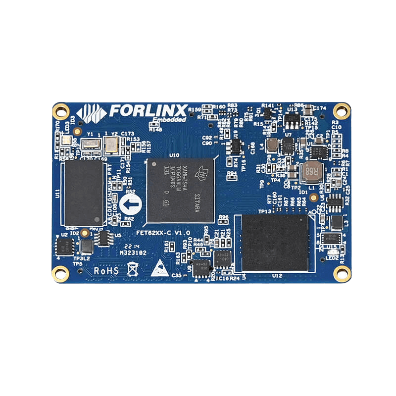
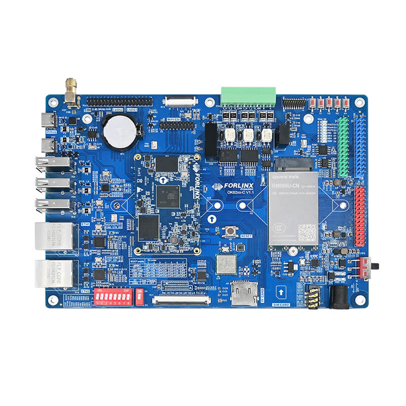
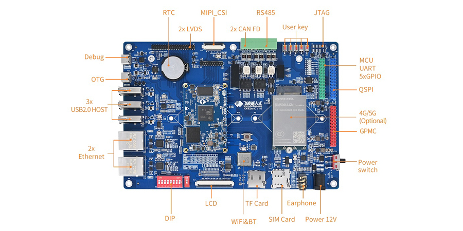
AM62x processor, as a new generation of high-performance and low-power processor, has been widely used in industrial control, human-computer interaction, edge computation and other fields. OK62xx-C development board based on AM62x processor provides abundant hardware interface resources for developers. This article will provide systematic troubleshooting ideas and solutions for various interface problems that may be encountered in the development process to help developers quickly locate and solve problems.
General Troubleshooting
In the process of hardware debugging, the systematic troubleshooting method can significantly improve the efficiency. The following is the general troubleshooting process:
Chip consistency verification:
First, make sure that the functional chip used is exactly the same as the reference design schematic. If the chip model is different, driver migration may be required, including modifying the device tree configuration and driver.
1. Basic signal checking:
For modules that fail feature verification, check in order:
- Whether the power supply voltage is within the allowable range;
- Check whether the reset signal timing meets the requirements;
- Check whether the frequency and amplitude of the clock signal are normal.
2. Cross Test:
By replacing either the System on Module (SoM) or the carrier board, quickly identify the source of the problem.
3. Signal integrity check:
- Measure whether the pin level is as expected;
- Check whether the data signal is output normally;
- Confirm whether the signal idle state is normal
4. Welding quality inspection:
- Check the welding problems, whether the resistance and capacitance devices have problems such as cold welding, continuous welding, missing welding, wrong welding, etc;
- Check the welding direction of the device to see if there is a problem that the pin 1 of the welded device does not correspond to the pin 1 of the carrier board.
5. Pin Multiplexing Checking:
Refer to the AM62x Technical Reference Manual to confirm whether the function multiplexing configuration of the used pins is correct. Pay special attention to the default functions of the pins related to startup.
Troubleshooting of System Failure to Start
Follow the steps below to troubleshoot the issue of system failure to start:
1. Key signal inspection:
- Measure the VCC3V3_SYS-PG (RD60) signal to ensure that the power supply is functioning properly;
- Check if all power rail voltages are within the allowable range;
- Verify whether the timing of the reset signal meets the requirements of the processor.
2. Start Configuration Check:
- Confirm that the GPMC bus related startup pins have been correctly pulled up and down in the carrier board design;
- Pay special attention to not affecting the startup configuration level when connecting external devices such as FPGA;
- Check the level status of the boot mode selection pin.
3. I2C bus conflict troubleshooting:
- RU50 and RU52 are I2C0 buses, and the SoM may have multiple devices mounted;
- Ensure that the bottom board does not float these pins, and other functions do not reuse I2C0;
- Check if the pull-up resistor on the I2C bus is normal.
4. Cross Test:
Replace the SoM or carrier board and confirm if it is an isolated issue.
Troubleshooting of I2C Interface Issues
Common problems and solutions of I2C bus:
1. Basic configuration check:
- Confirm that both SCL and SDA lines have pull-up resistors;
- Check if there are any conflicts in the addresses of devices mounted on the I2C bus within the same group.
2. Signal quality analysis:
- Measure whether the idle state is at a high level;
- Observe whether the waveform is complete and whether there is overshoot or ringing during data transmission;
- Use a logic analyzer to capture the complete communication process.
3. Impedance matching adjustment:
If the rising edge of the waveform is slow, the pull-up resistance value can be reduced;
If the low level is too high, the pull-up resistor value can be increased.
4. Diagnostic tool usage:
Use the I2Ctool tool to check if any devices are mounted on the bus:
i2cdetect-l//Check how many groups of I2C are on the system
i2cdetect-r-y2//Detect mounted devices on the I2C second set of buses
Troubleshooting of SPI Interface Issues
Key points for troubleshooting SPI communication faults:
1. Confirmation of hardware connections:
- MOSI and MISO must be cross-connected;
- Confirm that the chip select signal is correctly connected and not multiplexed by other functions;
- Check if the SPI clock line is connected.
2. Verification of mode configuration:
- Confirm that the CPOL and CPHA settings of the master and slave devices are consistent;
- Check if the clock frequency is within the range supported by the device;
- Verify if the data bit width setting is correct.
3. Signal measurement:
- Use an oscilloscope to measure the quality of the clock signal;
- Observe the signal changes on the data line during the active period of the chip select signal;
- Check the level states of each signal line in the idle state.
Troubleshooting of USB Interface Issues
Common problems with USB interfaces (2.0/4G/5G):
1. Power supply check:
- Measure whether the USB_VBUS_3V3 signal is a stable 1.8V;
- Confirm that the VBUS current supply capacity meets the device requirements.
2. Confirmation of signal connections:
Confirm that an AC coupling capacitor is connected in series with the USB transmission signal.
3. Special notes for USB:
Generally, an AC coupling capacitor has already been added to the transmission signal of the USB device end, so the receiving end does not need to add another coupling capacitor;
Check of level configuration:
Troubleshooting of SDIO Issues
1. Optimization of signal integrity:
- The pin levels of the SDIO interface are related to the transmission speed. The default operating voltage is 3.3V, and it needs to be switched to 1.8V in high-speed mode;
- The SDIO signal cannot pass through a level conversion chip and must be directly connected.
2. Optimization of signal integrity:
Confirm that the SDIO bus has been subjected to equal-length processing.
3. Pull-up resistor configuration:
- Configure appropriate pull-up resistors according to the specifications;
- Check the level state of the card detection pin.
The above are the common problem types and troubleshooting ideas during the development process of the OK62xx-C development board. This article first introduces six major types of problems, including general ideas, non-startup problems, I2C interface problems, SPI interface problems, USB problems, and SDIO problems. Subsequently, problems with interfaces such as LVDS, PCIe, UART, and CAN and their solution ideas will also be introduced. We hope that you will continue to pay attention.