Hardware Control of U-Boot Based on RK3576: Modification and Practice of Linux 6.1.84 Kernel Device Tree
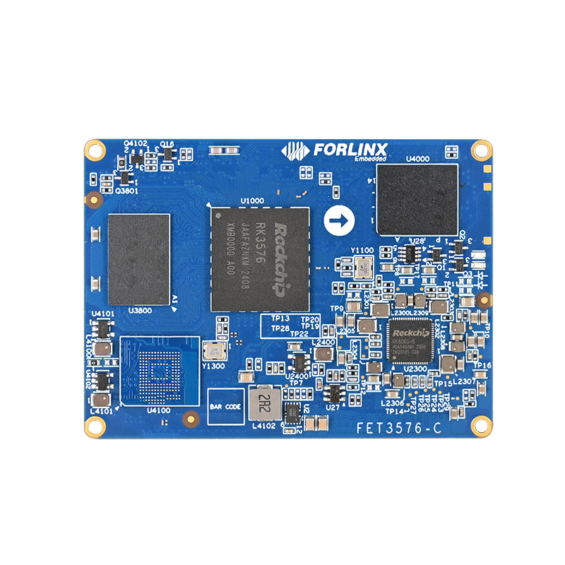
Forlinx Embedded RK3576 development board
1. Overview
This article introduces a method to pull up the GPIO during the U-Boot stage on the Forlinx Embedded OK3576-C development board by modifying the kernel device tree. As a high-performance embedded platform based on the RK3576 processor, the OK3576-C integrates a quad-core Cortex-A76 and a quad-core Cortex-A55 architecture, providing powerful computing support for scenarios such as industrial control and edge computing. Its flexible hardware configuration and complete software ecosystem enable such low-level hardware control requirements to be achieved through standardized device tree configuration without complex low-level code modification.
For application scenarios that require controlling peripherals during the early stage of system startup (U-Boot stage), such as enabling industrial sensors and resetting peripherals, the method presented in this article can effectively simplify the development process. If more precise control of the GPIO is required (such as precise timing adjustment and multi-state switching), direct modification of the U-Boot code is still necessary.
This article is verified based on Forlinx's official document ''OK3576 - C_Linux6.1.84_User Materials_R2'', which includes a comprehensive hardware manual, driver development guide, and sample code. This document is available on the Forlinx Embedded official website. This method can be referred to for other RK platforms (such as RK3568 and RK3588) or other Linux versions, but the pin definitions and device tree nodes need to be adjusted according to the specific hardware manual.
2. Objective Definition
Before modifying the U - Boot or kernel device tree, it is necessary to clarify the rationality of the requirements to avoid ineffective development. The main focus is to assess whether "pulling up the GPIO during the U-Boot stage" can satisfy the hardware design requirements. The critical factor is the GPIO level state at the initial power-on phase of the hardware.
If the hardware circuit necessitates ''pulling up the GPIO immediately after power-on'' (for example, for relay control or activating key modules), and the initial state of the target GPIO after power-on is low, this issue cannot be addressed through software solutions. The hardware design needs to be updated to select a GPIO pin that defaults to a high level after power-on, as determined by the hardware circuit. This is important because U-Boot typically begins operating 2 seconds after power-on, and the software cannot control the GPIO level before U-Boot starts.
2.1 GPIO Pin Selection Method
The Forlinx Embedded RK3576 development board offers abundant GPIO resources across various groups, catering to the control requirements of multiple peripherals. The following methods need to be used to confirm the initial power - on state and functional compatibility of the GPIO pins:
To check the hardware design documentation, refer to the Forlinx RK3576 development board, which includes a comprehensive pin function table and a schematic diagram of the carrier board. You can contact Forlinx Embedded's online customer service to obtain the download link for this documentation. Each pin is clearly labeled with its default level, direction (input/output), and voltage domain (e.g., 3.3V, 1.8V).
Measure and verify using a multimeter or oscilloscope to determine the pin level at power-on. Record the initial state (high or low) and the stabilization time.
| Connector Pin Number | CPU Ball Number | SoM Pin Function | Development Board Pin Function | Pin Direction Selection | Voltage Domain Voltage | Development Board Pin Function Description | Development Board Application Interface | Reset State |
| LD5 | A208 | PWM1_CH0_M0 | PWM1_CH0_M0 | Output | 3.3V | PWM1_CH0_M0 | - | Low level |
| LD6 | — | — | — | — | — | — | — | — |
| LD7 | 1U24 | UART0_TX_M0_DEBUG | UART0_TX_M0_DEBUG | Output | 3.3V | UART0 sending | UART0_TX_M0_DEBUG | High level |
| LD8 | — | GND | GND | — | — | GND | GND | — |
| LD9 | AA28 | UART0_RX_M0_DEBUG | UART0_RX_M0_DEBUG | Input | 3.3V | UART0 receiving | UART0_RX_M0_DEBUG | High level |
| LD10 | — | — | — | — | — | — | — | — |
| LD11 | 1W24 | I2C2_SCL_M0 | I2C2_SCL_M0 | Output | 3.3V | I2C2 clock | I2C2_SCL_M0 | Low level |
| LD12 | — | — | — | — | — | — | — | — |
| LD13 | 1W22 | PWM0_CH0_M0 | PWM0_CH0_M0 | Output | 3.3V | PWM0_CH0_M0 | PWM0_CH0_M0(MIPI screen backlight PWM) | Low level |
Figure1: RK3576 Development Board Interface Diagram
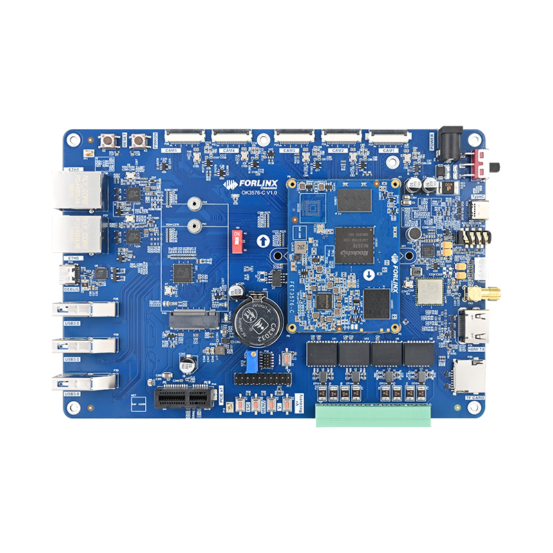
Figure2: RK3576 Development Board Interface Diagram
This method can be applied in various scenarios for the OK3576-C development board, including reset control for industrial sensor modules, enabling power-on for peripherals, and hardware initialization for custom expansion boards. It does not require immediate activation after power-on; instead, it simply needs the GPIO level to stabilize before the kernel driver is loaded during the U-Boot stage. The RK3576 development board supports wide - temperature operation (-40°C to 85°C), which is particularly suitable for such hardware control requirements in industrial environments.
3. Modification and Verification Methods
This section uses GPIO2_B4, the PCIE0_PERSTn pin from the PCIe interface on the OK3576-C - C carrier board, as an example to detail the steps for modifying the device tree and verifying the methods. The RK3576 development board features a PCIe 3.0 interface that allows for the expansion of high-speed peripherals. This article explains how to control the reset state of PCIe devices during the initial phase of system startup.
3.1 Pre - preparation
Hardware: OK3576 - C development board (SoM + carrier board), PCIe interface device (optional), multimeter, debugging serial cable.
Software: Linux 6.1.84 SDK, cross - compilation toolchain, serial terminal tool (such as SecureCRT, MobaXterm). The SDK contains complete compilation scripts and sample code.
Measurement point: GPIO2_B4 corresponds to the R354 resistor on the carrier board (between the PCIe socket and the electrolytic capacitor).
3.2 Verification of the Original State
First, flash the original factory default image to verify the original level change of GPIO2_B4:
Connect the debugging serial cable and open the terminal tool (baud rate 115200, 8N1). The Forlinx Embedded RK3576 development board has a debugging serial port led out by default, which is convenient for development and debugging.
Power on the development board, observe the serial port printing, and record the level change of GPIO2_B4 (measured by a multimeter).
By default, this pin will be pulled up after the kernel starts, and remains low during the U - Boot stage.
Figure 3: OK3576 Development Board (the red frame marks the PCIe interface area)
3.3 Entering Uboot Command Line
When the following prompt appears at the serial port terminal during power-on, press CTRL + C to enter the uboot command line (at this time, uboot does not transfer control to the kernel, and the GPIO level at the uboot stage can be measured):
Hit key to stop autoboot('CTRL+C'): 0
---------------------------------------------
		0:Exit to console
		1:Reboot
		2:Display type
---------------------------------------------
The uboot of the Forlinx Embedded RK3576 development board has been optimized by Forlinx, providing rich debugging commands and configuration options, and supporting the configuration of various startup parameters through environment variables, which is convenient for developers to perform low - level hardware debugging.
3.4 Theoretical Basis (RK U - Boot DTB Mechanism)
According to the ''Kernel - DTB'' section of RK's official manual ''Rockchip_Developer_Guide_UBoot_Nextdev_CN.pdf,'' the RK platform supports the use of the kernel DTB to initialize U-Boot peripherals. The core mechanism is as follows:
The native U - Boot only supports using its own DTB. The RK platform adds support for the kernel DTB mechanism, that is, using the kernel DTB to initialize peripherals. The main purpose is to be compatible with peripheral board - level differences, such as power, clock, and display.
The functions of the two are as follows:
U - Boot DTB: Responsible for initializing core devices such as storage and the printing serial port;
Kernel DTB: Responsible for initializing devices other than storage and the printing serial port (such as GPIO, I2C, and PCIe);
During U - Boot initialization, the U - Boot DTB is first used to complete the initialization of storage and the printing serial port, and then the Kernel DTB is loaded from the storage and used to continue initializing the remaining peripherals. The code implementation of the Kernel DTB is in the function: init_kernel_dtb() 。
Developers usually do not need to modify the U-Boot DTB, except when changing the printing serial port. The defconfig included in the SDKs released by each platform has already enabled the kernel DTB mechanism. So usually, for DTS modifications of peripherals, users should modify the kernel DTB.
The SDK of the RK3576 development board enables this mechanism by default, allowing developers to control the hardware during the uboot stage by modifying the kernel device tree, greatly simplifying the development process.
3.5 Kernel Device Tree Modification (Core Step)
By modifying the kernel device tree and adding a GPIO pull - up node, the GPIO can be controlled during the U - Boot stage. The specific modifications are as follows (based on the arch/arm64/boot/dts/rockchip/OK3576-C-common.dtsi file in the SDK):
  --- a/arch/arm64/boot/dts/rockchip/OK3576-C-common.dtsi
  +++ b/arch/arm64/boot/dts/rockchip/OK3576-C-common.dtsi
  @@ -428,6 +428,16 @@ wifi_ext_clk: wifi_ext_clk {
  pinctrl-0 = <&net_5g_pwr_gpio>;
  status = "okay";
  };
  +
  + gpio2b4_high_test {
  + compatible = "regulator-fixed"; // Compatible with fixed voltage regulator drivers (for GPIO pull-up)
  + gpio = <&gpio2 RK_PB4 GPIO_ACTIVE_HIGH>; // Specify GPIO2 _ B4, active high
  + enable-active-high; // Enable signal is high
  + regulator-boot-on; //Enabled at system boot (uboot phase in effect)
  + regulator-always-on; // Keep normally on (prevent being turned off by subsequent drive)
  + status = "okay"; // Enable the node
  + };
  +
  };
  @@ -1164,7 +1174,7 @@ rgmii_phy1: phy@2 {
  };
  &pcie0 {
  - reset-gpios = <&gpio2 RK_PB4 GPIO_ACTIVE_HIGH>; // Original PCIe reset GPIO definition
  + //reset-gpios = <&gpio2 RK_PB4 GPIO_ACTIVE_HIGH>; // Comment out to avoid pin conflict
  rockchip,skip-scan-in-resume;
  pinctrl-names = "default";
  status = "okay";
The device tree for the RK3576 development board has been optimized to clearly separate the configurations of different functional modules, making it easier for developers to make targeted modifications. The above modification method is also applicable to the control requirements of other GPIO pins. You just need to replace the corresponding GPIO group and pin numbers.
3.6 Compilation and Verification
Compile the kernel: Refer to the ''OK3576 - C Linux Compilation Manual'' provided in the SDK. You can use the compilation script (build.sh) optimized by Forlinx to quickly complete the compilation and generate a new boot.img (including the modified device tree).
Flash the image: Use an RK flashing tool (such as RKDevTool) to separately flash the boot.img to the development board. The Forlinx Embedded RK3576 development board supports multiple flashing methods such as TF card, USB, and network, which facilitates development and debugging.
Level verification:
After power - on, immediately use a multimeter to measure the voltage levels across the R354 resistor.
Enter the uboot command line (CTRL + C) and observe whether the voltage level remains high (if it is high, the modification takes effect).
Continue to start the kernel and confirm that the voltage level remains stable (without abnormal drops).
4. Advantages and Summary of the OK3576 - C Development Board
The OK3576-C is a high-performance development platform created by Forlinx Embedded and is based on the RK3576. It delivers robust computing capabilities while enabling low-level hardware control through well-designed hardware and software support. This method employs the kernel Device Tree Blob (DTB) mechanism in RK U-Boot. It enables the adjustment of the GPIO level during the U-Boot phase without requiring any modifications to the U-Boot code. This approach is suitable for scenarios where control accuracy is not a high priority.
Along with the GPIO control function discussed in this article, the OK3576 offers several additional advantages, making it an excellent choice for industrial control, smart devices, and other applications.
Powerful processing performance: It features a quad - core Cortex - A76 (2.2GHz) + quad - core Cortex - A55 (1.8GHz) architecture, supporting the NEON and FPU instruction sets to meet complex computing requirements.
Rich peripheral interfaces: It includes high - speed interfaces such as PCIe 3.0, SATA 3.0, dual - gigabit Ethernet, MIPI - CSI, and MIPI - DSI, supporting the expansion of various peripherals.
Complete software ecosystem: It supports operating systems such as Linux and Android, and provides a complete SDK and development documentation, reducing the development threshold.
Industrial - grade design: It supports a wide temperature range (- 40°C to 85°C) and has strong anti - interference ability, suitable for industrial environments.
Professional technical support: It provides full - process technical support for customers from hardware design to software development.
The key points of this method are as follows:
Hardware priority: Confirm the initial state of the GPIO after power - on to avoid conflicts between the requirement of ''raising the level immediately after power - on'' and the software control timing.
Node configuration: Use the regulator - fixed compatible driver and ensure it takes effect during the U - Boot phase through regulator - boot - on.
Conflict avoidance: Comment out other references to the same GPIO in the original device tree (such as PCIe reset - gpios) to prevent pin multiplexing conflicts.
Actual measurement verification: It is necessary to confirm the stability of the GPIO voltage level during the U - Boot and kernel phases using a multimeter or oscilloscope.
Forlinx Embedded provides complete technical materials and example codes for the OK3576-C development board, including hardware design manuals, driver development guides, and application development examples.