Implementation Scheme for I²C Operation during Linux 4.9 System Startup on T507 Platform
1. Product Configuration
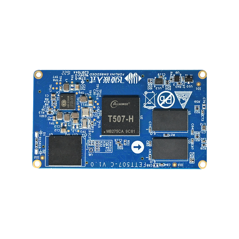
Product: T507
Hardware Configuration: v1.1
Software Configuration: Linux 4.9
2. Requirement Description
The SoM needs to send an initialization sequence viaI²C.
The registers of the temperature sensor need to be configured viaI²C.
3. Specific Implementation
U-Boot Phase
In the U - Boot phase, it can be added to the board - levelinitialization file.
In the ft_board_setup function, there is some content for audio chipinitialization.
Specific Steps:
Bus Initialization
① First, the pin functions need to be set.
Enable the bus.
② Switch the bus.
After switching the bus, all subsequent read and write operationswill be performed on this bus.
Suppose there are three I²C buses, numbered 3, 4, and 5, and theirnumbers in the U - Boot phase are 0, 1, and 2 respectively.
③ Perform i2c read/write operation according to chip timing.
④ The encapsulated functions of the system can also be used.
Specific Operations:
Kernel Phase:
If it is just simple read and write operations, it does not need torely on the device tree.
Directly obtain the i2c adapter information in the entry function.The implementation of the write function is as follows.
Implementation of Writing a Function
static s32 aim955_i2c_write(struct i2c_adapter *client, unsigned short devID, unsigned char regadr, unsigned char regVal) {
struct i2c_msg msg;
s32 ret = -1;
s32 retries = 0;
static unsigned char cmdBuf[4];
memset(cmdBuf, 0x00, 4);
cmdBuf[0x00] = regadr;
cmdBuf[0x01] = regVal;
msg.flags = !I2C_M_RD;
msg.addr  = devID;
msg.len   = 0x02;
msg.buf   = cmdBuf;
while(retries < 5) {
ret = i2c_transfer(client, &&msg, 1);
if (ret == 1) {
break;
} else {
retries++;
}
}
if((retries >= 5)) {
pr_err("write AIM error device ID %d regaddr = %d value = %d\n", devID, regadr, regVal);
}
return ret;
}
Examples:
aim955_i2c_write(client, 0x0C, 0x14, 0x10);
The parameter contains the bus information device address registeraddress register value.
11-14: Initialize the msg structure, fill in flag bits, deviceaddress, and register information
17-22: Send msg information through i2c_transfer function
Driver Examples:
#include <linux/module.h>
#include <linux/i2c.h>
#include <linux/init.h>
#include <linux/kernel.h>
#include <linux/delay.h>
#define DEVICE_ADDRESS 0x5d
static struct i2c_board_info __initdata my_i2c_device = {
I2C_BOARD_INFO("my_i2c_device", DEVICE_ADDRESS),
};
static s32 aim955_i2c_write(struct i2c_adapter *client, unsigned
short devID, unsigned char regadr, unsigned char regVal) {
struct i2c_msg msg;
s32 ret = -1;
s32 retries = 0;
static unsigned char cmdBuf[4];
memset(cmdBuf, 0x00, 4);
cmdBuf[0x00] = regadr;
cmdBuf[0x01] = regVal;
msg.flags = !I2C_M_RD;
msg.addr = devID;
msg.len = 0x02;
msg.buf = cmdBuf;
while(retries < 5) {
ret = i2c_transfer(client, &msg, 1);
if (ret == 1) {
break;
} else {
retries++;
}
}
if((retries >= 5)) {
pr_err("write AIM error device ID %d regaddr = %d value = %d\n",
devID, regadr, regVal);
}
return ret;
}
static s32 aim955_i2c_read(struct i2c_adapter *client, unsigned short
devID, unsigned char regadr, unsigned char *regVal) {
struct i2c_msg msgs[2];
s32 ret=-1;
s32 retries = 0;
static unsigned char readAddr[4];
memset(readAddr, 0x00, 4);
readAddr[0] = regadr;
msgs[0].flags = !I2C_M_RD;
msgs[0].addr = devID;
msgs[0].len = 1;
msgs[0].buf = readAddr;
msgs[1].flags = I2C_M_RD;
msgs[1].addr = devID;
msgs[1].len = 1;
msgs[1].buf = regVal;
while(retries < 5) {
ret = i2c_transfer(client, msgs, 2);
if(ret == 2) {
break;
} else {
retries++;
}
}
if((retries >= 5)) {
pr_err("read AIM error device ID %d regaddr = %d error!\n", devID,
regadr);
}
return ret;
}
static void aim955_devInit(struct i2c_adapter *client) {
unsigned char data_rec=0;
int iloop = 0x00;
//Each step of cgc, 955 configuration
aim955_i2c_write(client, 0x0C, 0x01, 0x02);
mdelay(4);
aim955_i2c_write(client, 0x0C, 0x14, 0x10);
mdelay(4);
aim955_i2c_write(client, 0x0C, 0x87, 0x02);
mdelay(4);
aim955_i2c_write(client, 0x0C, 0x06, 0x59);
mdelay(4);
aim955_i2c_write(client, 0x0C, 0x39, 0x84);
mdelay(4);
aim955_i2c_write(client, 0x0C, 0x41, 0x84);
mdelay(4);
aim955_i2c_write(client, 0x0C, 0x3A, 0xA2);
mdelay(4);
aim955_i2c_write(client, 0x0C, 0x42, 0xA2);
mdelay(4);
aim955_i2c_write(client, 0x0C, 0x3c, 0x00);
mdelay(4);
aim955_i2c_write(client, 0x0C, 0x44, 0x00);
mdelay(4);
aim955_i2c_write(client, 0x0C, 0x37, 0x0a);
mdelay(4);
aim955_i2c_write(client, 0x0C, 0x3f, 0x0a);
mdelay(4);
aim955_i2c_write(client, 0x0C, 0x9C, 0x10);
mdelay(4);
aim955_i2c_write(client, 0x0C, 0x9D, 0x03);
mdelay(4);
aim955_i2c_write(client, 0x0C, 0x03, 0xea);
mdelay(4);
//Configure the init_in of AIM956
aim955_i2c_write(client, 0x2C, 0xc6, 0x95);
mdelay(4);
aim955_i2c_write(client, 0x2C, 0xD1, 0x43);
mdelay(4);
aim955_i2c_write(client, 0x2C, 0xD2, 0x40);
mdelay(4);
aim955_i2c_write(client, 0x2C, 0xD4, 0x40);
mdelay(4);
//Second step 2222 mode
aim955_i2c_write(client, 0x2C, 0xA2, 0x18);
mdelay(4);
//A delay of 10ms is required here
aim955_i2c_write(client, 0x2C, 0xA1, 0x1A);
mdelay(4);
aim955_i2c_write(client, 0x0C, 0xB1, 0x1A);
mdelay(30);
aim955_i2c_write(client, 0x0C, 0xB2, 0x18);
mdelay(15);
// Step 3: TP address mapping. // Address of the transparent IIC.
// The 0x70 register and the 0X77 register are a paired group and
must have the same slave address.
aim955_i2c_write(client, 0x0C, 0x70, 0xBA);
mdelay(4);
aim955_i2c_write(client, 0x0C, 0x77, 0xBA);
mdelay(4);
// The 7-bit slave address of the tp chip is 0x5d, and the 8-bit
slave address is 0xba.
aim955_i2c_write(client, 0x0C, 0x71, 0x28);
mdelay(4);
aim955_i2c_write(client, 0x0C, 0x78, 0x28);
mdelay(4);
// Use registers to identify 956.
aim955_i2c_write(client, 0x2C, 0x07, 0x19);
mdelay(4);
// Modify the SCL frequency of 956 as an I2C Master to 400KHz
(default is 180KHz).
aim955_i2c_write(client, 0x2C, 0x26, 0x35);
mdelay(4);
// Modify the SCL frequency of 956 as an I2C Master to 400KHz
(default is 180KHz).
aim955_i2c_write(client, 0x2C, 0x27, 0x35);
mdelay(4);
// Step 4: Configuration optimization.
aim955_i2c_write(client, 0x0C, 0xB6, 0xC0);
mdelay(4);
aim955_i2c_write(client, 0x0C, 0x33, 0x16);
mdelay(4);
aim955_i2c_write(client, 0x0C, 0x8B, 0x09);
mdelay(4);
aim955_i2c_write(client, 0x0C, 0x2C, 0x00);
mdelay(4);
aim955_i2c_write(client, 0x0C, 0x2B, 0x07);
mdelay(4);
for (iloop = 0x00; iloop < 8; iloop++) {
aim955_i2c_write(client, 0x0C, 0xB7, 0xfa);
mdelay(4);
aim955_i2c_write(client, 0x0C, 0xB7, 0xff);
mdelay(4);
}
aim955_i2c_write(client, 0x0C, 0x8b, 0x01);
mdelay(4);
aim955_i2c_write(client, 0x0C, 0x33, 0x06);
mdelay(4);
aim955_i2c_write(client, 0x0C, 0x2C, 0x04);
mdelay(4);
//Step 5: Configure IO. set p1 for 955 according to actual
requirements
aim955_i2c_write(client, 0x0C, 0x1E, 0x01);
mdelay(30);
//The GPIO-0 of AIM955 is set to Inputt and is only configured when
applying DGPIO
aim955_i2c_write(client, 0x0C, 0x0D, 0x03);
mdelay(4);
//The GPIO_1/2 of AIM955 is set to Inputt and is only configured when
applying DGPIO
aim955_i2c_write(client, 0x0C, 0x0E, 0x33);
mdelay(4);
//The GPIO-3 of aim955 is set to Inputt and is only configured when
applying DGPIO
aim955_i2c_write(client, 0x0C, 0x0F, 0x03);
mdelay(4);
aim955_i2c_write(client, 0x0C, 0x10, 0x33);
mdelay(4);
aim955_i2c_write(client, 0x0C, 0x11, 0x33);
mdelay(4);
// Set P0,
aim955_i2c_write(client, 0x2C, 0x34, 0x01);
mdelay(4);
//GPIO0
aim955_i2c_write(client, 0x2C, 0x1D, 0x05);
mdelay(4);
//GPIO1/2 GPO1/2 input from AIM955
aim955_i2c_write(client, 0x2C, 0x1E, 0x55);
mdelay(4);
//GPIO3 input--from tp chip
aim955_i2c_write(client, 0x2C, 0x1F, 0x05);
mdelay(4);
aim955_i2c_write(client, 0x2C, 0x20, 0x55);
mdelay(4);
aim955_i2c_write(client, 0x2C, 0x21, 0x55);
mdelay(4);
//Step 6 Configure REMinitB
aim955_i2c_write(client, 0x0C, 0xC6, 0x21);
mdelay(4);
//Read the value of IIC register
aim955_i2c_read(client, 0x0C, 0xC7, &data_rec);
mdelay(4);
// Step 7
aim955_i2c_write(client, 0x0C, 0x03, 0xDA);
mdelay(4);
aim955_i2c_write(client, 0x0C, 0x50, 0x16);
mdelay(30);
}
static void aim955_setIO(struct i2c_adapter *client){
aim955_i2c_write(client, 0x0C, 0x1E, 0x01);
mdelay(30);
aim955_i2c_write(client, 0x0C, 0x0F, 0x05);
mdelay(4);
aim955_i2c_write(client, 0x2C, 0x34, 0x01);
mdelay(10);
aim955_i2c_write(client, 0x2C, 0x1F, 0x03);
mdelay(4);
}
static int __init my_driver_init(void)
{
struct i2c_adapter *adapter;
//Get I2C adapter
adapter = i2c_get_adapter(4);
if (!adapter) {
pr_err("Unable to get I2C adapter\n");
return -ENODEV;
}
printk(" I2C adapter: %s\n\n\n\n\n\n\n\n", adapter->name);
aim955_devInit(adapter);
aim955_setIO(adapter);
return 0;
}
static void __exit my_driver_exit(void)
{
return 0;
}
module_init(my_driver_init);
module_exit(my_driver_exit);
MODULE_LICENSE("GPL");
MODULE_AUTHOR("Your Name");
MODULE_DESCRIPTION("Example I2C Driver without Device Tree");
Application phase
// Use the write and read system functions to operate on the devicefiles of the bus.
// When performing write operations on registers at the applicationlayer, values should be sent continuously in the form of a queue.
// If two separate write functions are used, an i2c stop signal willbe inserted in between, and the slave device cannot recognize the dataproperly.
Examples:
#include <stdio.h>
#include <stdlib.h>
#include <fcntl.h>
#include <sys/ioctl.h>
#include <linux/i2c-dev.h>
#include <unistd.h>
#include <string.h>
#include <math.h>
#include <errno.h>
#include <termios.h> /*PPSIX Terminal control definition*/
#include <linux/types.h>
#include <linux/i2c.h>
#define I2C_DEVICE_ADDRESS 0x29
#define I2C_REGISTER_ADDRESS 0x00
#define REGISTER_ADDR 0x001 // Register address
#define DATA_TO_WRITE 0x60
double binaryToDecimal(const char* binary) {
int length = strlen(binary);
double decimalValue = 0.0;
// Processing integer parts
for (int i = 0; i < length; i++) {
if (binary[length - 1 - i] == '1') {
decimalValue += pow(2, i);
}
}
return decimalValue;
}
double binaryFractionToDecimal(const char* binary) {
int length = strlen(binary);
double decimalValue = 0.0;
// Process the fractional part
for (int i = 0; i < length; i++) {
if (binary[i] == '1') {
decimalValue += pow(2, -(i + 1)); // The decimal index starts from
-1
}
}
return decimalValue;
}
void decToBinaryString(unsigned int hex, char *binaryStr, int length)
{
//Initialize character array to zero
for (int i = 0; i < length; i++) {
binaryStr[i] = '0';
}
binaryStr[length] = '\0'; //Set the terminator.
//Convert to binary
for (int i = length - 1; i >= 0; i--) {
if (hex & 1) {
binaryStr[i] = '1';
}
hex >>= 1; // Move right by one bit
}
}
int twosComplementToOriginal(int num, int bitWidth) {
if ((num >> (bitWidth - 1)) & 0x1) {
int mask = (1 << bitWidth) - 1;
num = ~num;
num = num + 1;
num = num & mask;
} else {
// If it is a positive number or zero, the complement code is the
same as the original code.
}
return num;
}
int printBits13To24(int n) {
unsigned int shifted = n >> 12;
unsigned int mask = 0xFFF; // The binary representation is 0000 1111
1111 1111 0000 0000 0000 0000
unsigned int result = shifted & mask;
for (int i = 11; i >= 0; --i) {
printf("%d", (result >> i) & 1);
}
printf("\n");
return result;
}
int main() {
//Open the I2C bus device.
int file;
char *filename = "/dev/i2c-1"; // The file path of the I2C bus
device.
char integerPart[9];
char fractionPart[5];
char binaryStr[13];
int value=0;
char write_buffer[2];
if ((file = open(filename, O_RDWR)) < 0) {
perror("Failed to open the I2C bus device.");
exit(1);
}
// Set the I2C device address.
if (ioctl(file, I2C_SLAVE, I2C_DEVICE_ADDRESS) < 0) {
perror("Unable to set device address");
close(file);
exit(1);
}
write_buffer[0] = REGISTER_ADDR; // Register address
write_buffer[1] = DATA_TO_WRITE;
if (write(file, write_buffer, 2) != 2) {
perror("Failed to write to the i2c bus");
close(file);
return 1;
}
unsigned char register_address = I2C_REGISTER_ADDRESS; // Defined and
assigned as a register address
int data;
if (write(file, ®ister_address, sizeof(register_address)) !=
sizeof(register_address)) {
perror("Write to register address failed");
close(file);
exit(1);
}
if (read(file, &data, sizeof(data)) != sizeof(data)) {
perror("Failed to read data");
close(file);
exit(1);
}
int binaryRepresentation = printBits13To24(data);
value=twosComplementToOriginal(binaryRepresentation, 12);
decToBinaryString(value, binaryStr, 12);
strncpy(integerPart, binaryStr, 8);
integerPart[8] = '\0';
// Extract 3 to 0 bit
strncpy(fractionPart, binaryStr + 8, 4);
fractionPart[4] = '\0';
double finalResult = binaryToDecimal(integerPart)+
binaryFractionToDecimal(fractionPart);
if((binaryRepresentation >> 11) & 0x1)
printf("temperature--:- %.2fcent\n",finalResult);
else
printf("temperature--: %.2fcent\n",finalResult);
//Close the I2C bus device.
close(file);
return 0;
}