


OK153-S12 Mini Single Board Computer
CPU: Allwinner T153
Architecture: 4x [email protected]+RISC-V E907@600MHz
Frequency: 1.6GHZ
RAM: 256MB DDR3,512MB DDR3
ROM: 256MB NandFlash,8GB eMMC
System: Linux 5.10
OK153-S12 Mini Industrial Single Board Computer(SBC) Based on Allwinner T153
OK153-S12 Mini single board computer(SBC) / development board is based on the Allwinner T153 industrial-grade processor, featuring rich interfaces such as RGMII, UART, CAN, and display to support diverse application scenarios. With a 10–15 year lifecycle, it ensures long-term supply stability for your products.
OK153-S12 Mini SBC
Raspberry Pi 40-Pin GPIO Interface
The OK153-S12 Mini board includes a Raspberry Pi–compatible 40-pin GPIO for easy connection to external hardware.
OK153-S12 Mini SBC Video
OK153-S12 Mini SBC: Low-Cost | 4*A7+RISC-V | RaspberryPi GPIO Header
▊ Hardware Features
|
FET153-S System on Module Basic Features |
|
|---|---|
| CPU | Allwinner T153 |
| ARM: | 4×Cortex-A7,up to 1.6GHz |
| RISC-V | E907, up to 600MHz |
| NPU: | No |
| GPU: | G2D |
| VPU: | No |
| RAM | 256MB/512MB/1GB DDR3 |
| ROM | 256MB/512MB NandFlash /8GB eMMC |
| Operating Temperature | -40℃~+85℃ |
| Working Voltage | DC 5V |
| Connection | Edge connector + LGA, with a total of 185 pins led out. The center-to-center spacing of the edging connecting pins is 0.4 mm. The pitch for LGA package is 0.47 mm. |
| OS version | Linux5.10 |
| Flashing | USB OTG |
| Dimensions | 44mm x 35mm |
|
FET153-S System on Module Functional Parameters |
||
|---|---|---|
| Function | Quantity | Parameter |
| Parallel CSI | ≤1 | Supports 8/10/12/16 bit wideth and BT.656 up to 2-ch 720P@30fps and BT.1120 up to 2-ch 1080P@30fps,RAW up to 4-ch720P@30fps |
| MIPICSI | ≤2 | Supports 4-lane/2+2-lane,Upto1.0Gbit/sperlane |
| MIPIDSI(1) | ≤1 | Supports 4-lane MIPI DSI, Up to 1920x1200@60fps,1.0Gbit/sperlane |
| RGBLCD(1) | ≤1 | DE/SYNC mode, up to 1920x1080@60fps;RGB888, RGB666 and RGB565 pixel |
| LVDS(1) | ≤2 | Up to 1920×1080@60fps for dual link; Up to 1366×768@60fps for single-link |
| SDIO | ≤2 | SMHC0 for SD card; SMHC1 for SDIO interface, 3.3 V mode only |
| Audio | ≤1 | Built-in audio codec supports 1 x differential LINEOUT output |
| IIS | ≤3 | Supports master/slave mode, sampling rate 8kHz to 384kHz; I2S0/2 supports 4lane application; I2S1 supports 2lane application |
| DMIC | ≤1 | Supports master/slave mode with sampling rate from 8kHz to 48kHz |
| OWAIN/OUT | ≤1 | Single line audio |
| USB2.0 DRD | 1 | Supports master and slave and High-Speed,480Mbps |
| USB2.0 HOST | 1 | Only supports master mode, and High-Speed, 480Mbps |
| GMAC | ≤3 | Supports RMII/RGMII interface and rate 10/100/1000 Mbit/s |
| CAN-FD | ≤2 | Supports CAN-FD(upto64databytes) and CAN2.0A CAN2.0B |
| LocalBus | ≤1 | Supports 8/16/32 bit width, up to 100MHz bus clock |
| SPI | ≤4 | Supports master/slave mode with up to 100MHz clock; SPI0, SPI2, SPI3 support SPI mode; SPI1 supports SPI mode and DBI mode |
| TWI | ≤5 | Compatible with I2C standard, standard mode 100kbit/s, fast mode 400kbit/s |
| UART(2) | ≤10 | Compatible with industry standard 16450/16550. |
| GPADC | ≤24 | 12-bit sampling resolution, maximum sampling rate 1MHz; GPADC2 has 4 channels multiplexed as TPADC |
| TPADC | ≤1 | 4-wire resistive touch, 12 bit SAR type AD conversion |
| PWM&PWMCS | ≤30 | PWM output frequency 0 ~ 24 MHz or 0 ~ 100MHz; PWMCS output frequency 0 ~ 4MHz, supporting maximum and minimum frequency limit |
| LEDC | ≤1 | Control LED light, programmable output high and low width, data up to 800kbit/s |
| IRTX | ≤1 | Infrared output |
| IRRX | ≤4 | Infrared receiving |
| GPIO | ≤140 | |
Note: The parameters in the table are hardware design or theoretical CPU values.
(1) MIPI-DSI have a pin multiplexing relationship, please read the chip data sheet or pin multiplexing table;
(2) UART0 is used as the debugging serial port. It is recommended to keep this design.
▊ Carrier Board
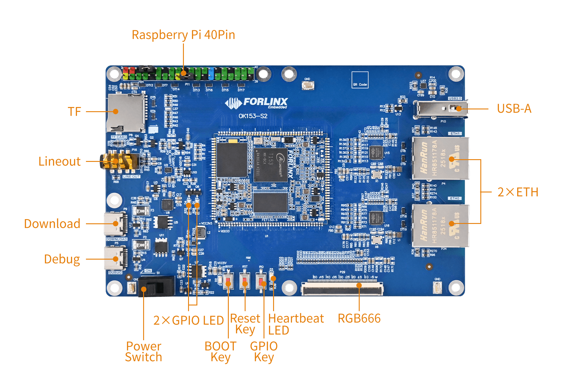
| OK153-S12 Mini Development Board Function Parameters | ||
|---|---|---|
| Function | Quantity | Parameter |
| LCD | 1 | RGB666 (18-bit) – The SoM can support up to RGB888 (24-bit) and a maximum resolution of 1080p@60fps. |
| Ethernet | 2 | 10/100/1000Mbps adaptive, J-45 interface |
| TYPE-C(DEBUG) | 1 | Convert debug UART to USB for CPUX debugging, also functions as the carrier board power interface. |
| TYPE-C(USB0) | 1 | Native USB0 interface, supports USB device mode, also serves as the carrier board power interface. |
| USB1 Host | 1 | Native USB1 interface, USB 2.0 (up to 480 Mbps). |
| TF | 1 | Supports SD 3.0 protocol, with support for high/low-speed card switching. |
| PWM | 1 | Connected for LCD backlight adjustment. |
| Audio | 1 | One 4-segment headphone connector with mono Lineout |
| KEY | 3 | Reset, download, and GPIO buttons |
| LED | 4 | 2 x GPIO-controlled LED, one heartbeat LED, and one power good indicator LED |
| Raspberry Pi | 1 | One set of 40-pin Raspberry Pi interface. |
▊ Accessories
Please click here to get more information about the supported modules and accessories.
▊ Documentation
Reference Manuals
Hardware Related
Product Datasheet
User Guide
Carrier Board Schematic
Carrier Board PCB
SoM Pinmux
Firmware Related
OS Image
Testing Demo
Source Code
Manual
Contact Us
Welcome to get in touch with us, our experts will reply to your email within 24 hours.
▊ How To Buy & Shipment
1. Order Online: We have an online store on Alibaba. Please contact us for details.
2. Order Offline: Send your inquiry to [email protected].
3. Payment Terms: 100% T/T in advance.
1. Delivery: Goods shipped by express upon receipt of payment.
2. Lead Time: Sample orders within 5 working days; bulk orders 6 weeks.
3. Shipping Charge: Buyers bear the shipping cost.
▊ Forlinx Recommended Products
Architecture: 3x [email protected]+1x Cortex-M0
Frequency: 1.5GHz
RAM: 256MB DDR3,512MB DDR3
ROM: 256MB NandFlash,512MB NandFlash
System: Linux 6.1
Architecture: 4x [email protected]+RISC-V E907@600MHz
Frequency: 1.6GHZ
RAM: 256MB DDR3,512MB DDR3,1GB DDR3
ROM: 256MB NandFlash,512MB NandFlash,8GB eMMC
System: Linux