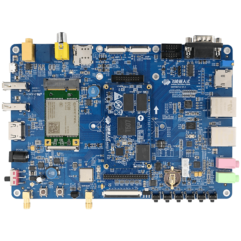
What Is OKT507-C Single Board Computer Based on Allwinner T507 SoC?
First, T507 chip introduction:
Allwinner T5 Series is a high-performance quad-core CortexTM-A53 processor for the next generation of automotive markets. The T5 series meets automotive AEC-Q100 testing requirements. The chip integrates quad-core CortexTM - A53 CPU, G31 MP2 GPU, multiplex video output interface (RGB/2 x LVDS/HDMI/CVBS OUT), multiplex video input interface (MIPI CSI/BT656/BT1120). The chip supports 4K@60fps H.265 decoding, 4K@25fps H.264 decoding, DI, 3D noise reduction, automatic color grading systems and trapezoidal correction modules to provide a smooth user experience and professional visuals.
The target applications are:
- Inlaid car entertainment system
- Inline digital clusters
- Inlaid high-definition panoramic images
- Head-up display and others
- Smart cockpit products
...
T5 Series Application Processor Block diagram
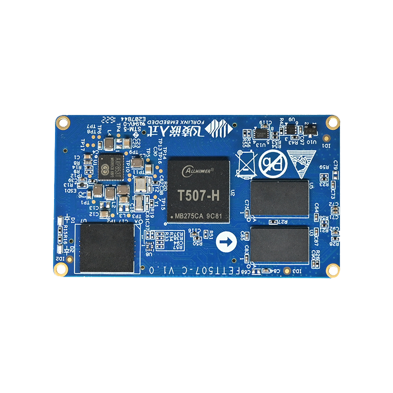
Second, FETT507-C SoM introduction
Forlinx embedded FETT507-C core board using the car-class processor T507, which passed the automotive AEC-Q100 test, more than 10 years of life cycle, Cortex-A53 architecture, main frequency 1.5GHz, integrated G31 GPU, memory 2GB DDR3L, storage 8GB eMMC. The whole board industrial-grade operation temperature is wide, supports most of the current popular video and picture format decoding, with stable and reliable industrial-grade product performance, low power consumption and rich user interface and other advantages, equipped with Linux, Android, Ubuntu operating system, suitable for automotive electronics, power, medical, industrial control, Internet of Things, intelligent terminals and other fields.
FETT507-C SoM Front
FETT507-C SoM Rear
Third, the table of T507 SoM’s entire power consumption under Linux system
|
Hardware Conditions |
Test Content |
Voltage (V) |
Operating Current |
|
|
Instant Peak Value (mA) |
Stable Value(mA) |
|||
|
The whole SBC |
With 4G module, HDMI and LCD display, CPU full load |
12±5% |
370 |
347 |
|
SOM |
No load power-on start-up |
5±5% |
450 |
260 |
|
CPU usage100% |
5±5% |
- |
448 |
|
Remarks:
1, Peak Current: the maximum current value during start-up
2, Stable value current: after start-up stay in the power-on interface when the current value.
Fourth, the minimum system schematic
Forlinx embedded development board takes into account most of the functional needs of most customers, is a universal design, with customers have formed a stable mode of cooperation: customer procurement of Forlinx embedded development board for product evaluation and development, and later according to the needs of the functional interface design and production of the base plate, Forlinx embedded to provide a stable core board. The design of the base plate is relatively simple compared to the core board, but in the actual communication, we often receive a lot of technical advice from users who do not have the experience of platform floor design. Therefore, our technicians specialize in providing considerations for the design of product substrates for each platform and the circuits that must be added, which we call "hardware minimum systems". The T507 base plate design minimum schematic is as follows.
In order to meet the normal work of the T507 core board, in addition to the power DCIN, also need SOC-RESET button, easy to debug, BOOT configuration circuit, easy to write and start the system, UART0 part of the circuit, easy to confirm whether the system is working properly, at the same time convenient for debugging, OTG, TF Card circuit, convenient system burning.
Fourth, T507 hardware design guide
1. The FETT507-C core board uses PMIC model AXP853T, AXP853T DCDC with leakage detection function, in the AXP853T-T507 hardware system is not powered on, such as Peripheral chip through the pull-up resistance or through the peripheral chip internal leakage to the AXP853T DC DC power rail, leakage voltage if more than 0.5V, then AXP853T will not start, waiting for leakage abnormal situation is lifted. For leak-proof design, read the SOC Leak-Proof Application Design Guide.
2. When using the USB Standby scenario, the VCC-USB2 requires external constant power. In the absence of a USB Standby scenario, VCC-USB2 hangs on the PMU DCDC1.
3. All GPIO can be suspended or grounded if not used. LRADC, GPADC does not use hoverable handling.
4. In the core board reset restart, if the bottom plate has a device not powered off causing the core board GPIO leakage, can be measured DCDC1 voltage, and DCDC1 voltage will make the base plate can not be powered off, because the bottom plate can not be powered down leading to GPIO leakage, will fall into the core board can not start the dead cycle! Our treatment is that the gate of Q1 NMOS uses DCDC1 differential voltage control, which can cause the bottom plate to lose power even if the leakage voltage on the DCDC1 is about 1V. Please refer to our board design.
5. Core plate cooling considerations:
After testing, the core plate without heat sink, at a high temperature of 85℃ operation, the main frequency will drop to 480MHz, if you add a small heat sink at 85℃ operation will not reduce the frequency. Therefore, OKT507-C substrate reserved 2 diameter 3.2mm heat sink installation holes, users can choose according to the field environment to install heat sink, heat sink and core plate contact surface please add a layer of insulated thermal silicone pad. The size of the heat sink is shown below:
Forlinx provides a wealth of hardware and software information, including T507 user manual, T507 core board schematic, base board schematic, core board pin definition and Allwinner official T507 chip processor data, etc., to help developers quickly complete the project product development.