Common Issues and Troubleshooting Ideas in the Development Process of the i.MX9352 SoM
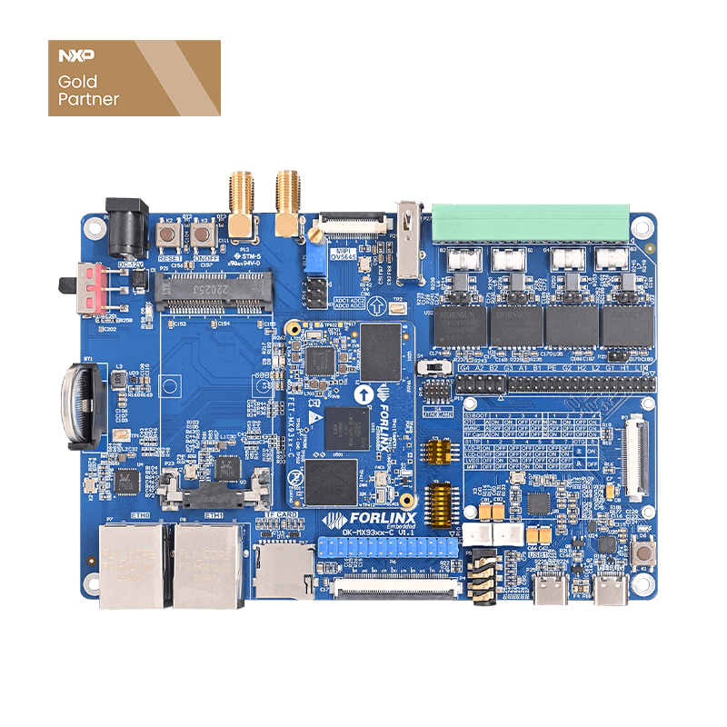
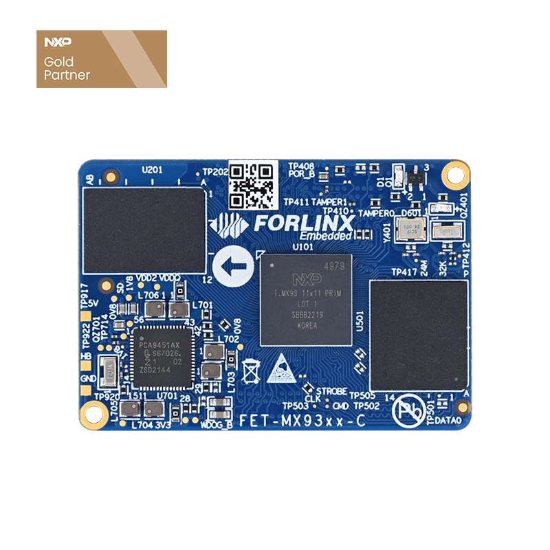
As a gold partner of NXP, Forlinx Embedded has launched several embedded main control products based on the i.MX series of application processors. In addition to the newly released i.MX95xx series of System on Modules (SoMs), the i.MX93xx series of SoMs—also part of the i.MX9 family—has been available on the market for many years and has gained recognition and preference from numerous customers.
Throughout the long-term technical support service process, Forlinx Embedded has compiled common issues and troubleshooting methods encountered by users developing the i.MX93xx series of products. This article aims to outline these experiences to help developers quickly identify problems and enhance the development efficiency.
General Troubleshooting Ideas
For troubleshooting the i.MX93xx series master control, follow these general steps for any abnormal functions:
1. Hardware Consistency Verification
- Ensure that the carrier board design is consistent with the schematic diagram. If the functional chip is replaced, the corresponding driver shall be transplanted;
- Check whether the power supply, reset, and clock of the functional chip are normal.
2. Cross-Test Positioning
- Determine the source of the problem by replacing the SoM or the carrier board.
3. Signal and Soldering Inspection
- Confirm that the pin levels are matched and the data signal output is normal.
- Check whether there are process problems such as cold soldering or bridging in the resistor and capacitor components.
4. Pin Multiplexing Configuration
- Verify whether the pin multiplexing settings are consistent with the functional requirements.
Common Issues and Solutions for Specific Modules
1. Non-startup Issue
- In addition to the power supply and reset, you need to confirm whether the PWR_EN signal is normal.
- Check whether the pull-up and pull-down resistors of the BOOT start pins on the carrier board are configured as required.
2. I2C Bus Issue
- Confirm whether a pull-up resistor is added to the I2C bus (open-drain output characteristic);
- Check whether there is an address conflict among devices in the same group;
- Measure the waveform: it should be at a high level in the idle state, and the waveform should meet the standard during data transmission;
- Adjust the resistance value of the pull-up resistor: if the rising edge is slow, reduce the resistance value; if the low level is too high, increase the resistance value;
- Use tools for detection:
i2cdetect -l  # Detect the I2C bus groups
i2cdetect -r -y 2  # Detect the devices on the second group of buses
3. SPI Communication Issue
- The MISO and MOSI of the SPI interface need to be connected correspondingly;
- Confirm that the chip-select signal (CS) is correctly connected;
- Verify whether the modes (such as CPOL and CPHA) of both communication parties are consistent;
- Measure whether the clock and data output are normal.
4. USB Interface Issue
- The USB_VBUS_3V3 signal must be 3.3V;
- Cross-connecting USB differential signal lines is strictly prohibited.
5. SDIO Interface Issue
- The pin level of the SD2 interface is related to the transmission speed. It is 3.3V by default and 1.8V in high-speed mode;
- The SDIO signal cannot have its pin level converted through a level-conversion chip;
- Check whether the SDIO bus has been treated for equal-length;
- Prioritize checking whether the clock output is normal.
6. LVDS Display Issue
- Confirm that the screen output mode (VESA/JEIDA) is consistent with the driver configuration.
7. Ethernet Network Issue
- Verify whether the PHY chip and the MAC interface mode (such as RGMII) are consistent and whether equal-length processing has been done;
- Check whether the pull-up resistor and the waveform of the MDIO bus are normal. Avoid bifurcated wiring;
- If the speed does not meet the requirements, you can check whether all power supplies and the reference ground are intact;
- Confirm that the center-tap connection of the network transformer is correct and there is no PHY address conflict on the same bus;
- Check whether the MDI data lines have been treated for equal-length and whether the impedance meets the requirements.
8. CAN Bus Issue
- When there are multiple devices on the CAN bus, please confirm whether there are 120-ohm matching resistors on the devices at both ends;
- If the CAN devices cannot communicate, please try to connect the reference grounds of the CAN devices to reduce common-mode interference.
9. UART Serial Port Issue
- The serial port transceiver signals need to be connected correspondingly;
- Confirm whether the serial port tool is configured correctly, such as the baud rate;
- Measure whether the data output is normal.
10. RS485 Issue
- When there are multiple devices on the RS485 bus, please confirm whether there are 120-ohm matching resistors on the devices at both ends;
- If the RS485 devices cannot communicate, please try to connect the reference grounds of the RS485 devices to reduce common-mode interference;
- Since RS485 is a half-duplex transmission, some RS485 chips require transceiver control signals. Please confirm whether the chip driver has been added.
11. Audio Issue
- Confirm whether the audio chip is recognized by the system through the I2C tool;
- Check the I2S data waveform and the audio output path (such as the power amplifier circuit).
12. GPIO Issue
- If the GPIO is multiplexed as a BOOT start pin, avoid adding pull-up or pull-down circuits when powering on, or isolate them through a buffer chip.
Summary
With a systematic troubleshooting idea and modular solutions, you can efficiently deal with common development problems such as interface communication, signal integrity, and configuration logic. It is hoped that the practical experiences summarized in this article can provide a clear problem-positioning path for developers and help projects be implemented quickly.