Practical Guide: Connect and Configure an SPI Screen on the OK3568 Embedded Platform
This article provides a detailed introduction on connecting and configuring an SPI screen in the Linux system, covering hardware wiring methods, steps for modifying the device tree, and driver adaptation techniques.
With the adaptation solution provided in this tutorial, the ST7735S screen can be quickly integrated with the Forlinx OK3568 development board, creating a cost - effective display solution for applications such as industrial control and portable devices.
If further expansion of functions is needed (such as touch control and backlight adjustment), additional development can be conducted based on this.
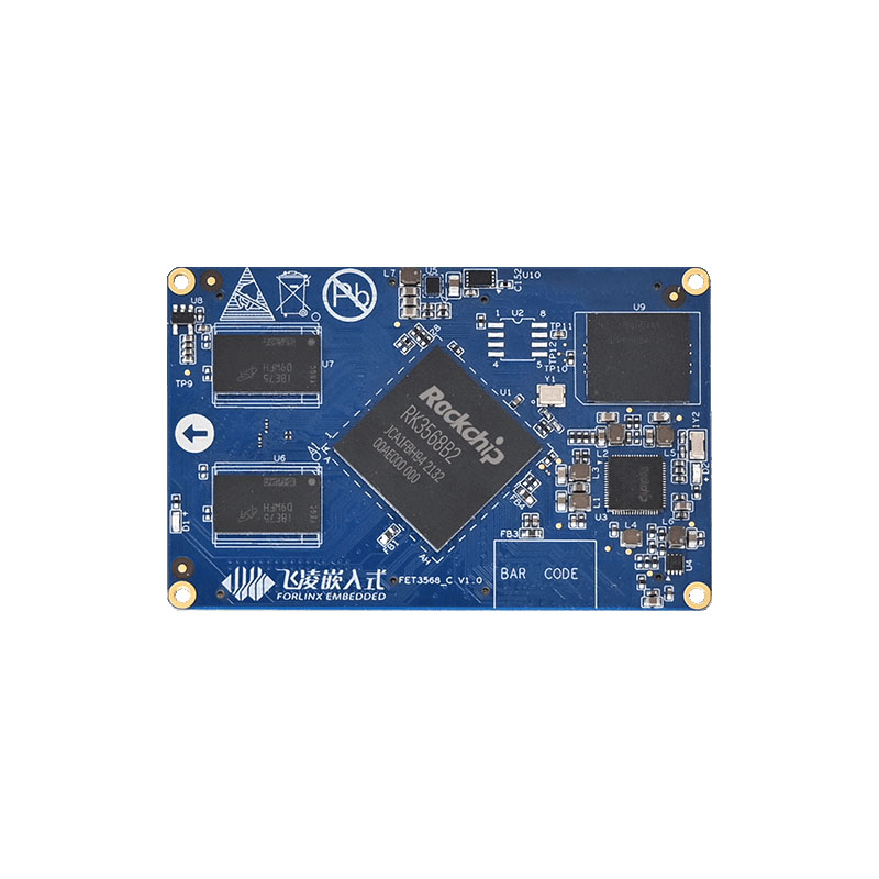
1. RK3568-spi Adaptation to 1.8-inch TFT Color Screen
Driver chip: : ST7735S
Resolution: 128×160, supporting 260,000 colors and 65K colors (16 - bit RGB565 format)
Interface Type: 4 - wire SPI (including CS/DC/RES/SCL/SDA pins), with independent backlight BL control
Operating Voltage: 3.3V (VCC pin, do not connect to 5V)
Communication Rate: Supports a maximum SPI clock of 50MHz
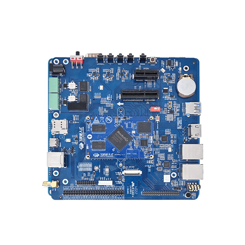
2. Hardware Connection
The connection relationship between the screen pins and the OK3568 must be strictly corresponding to ensure normal SPI communication and GPIO control.
The connection table is as follows:
| Screen Pin | Connected to OK3568 | Function Description | Notes |
|---|---|---|---|
| VCC | 3.3V power supply | Core operating voltage of the screen | Must be connected to 3.3V! Connecting to 5V will burn the chip. |
| GND | GND | Power supply common ground | Must be reliably grounded; otherwise, the display will be abnormal. |
| BL | 3.3V power supply | Screen backlight control | When not controlled by software, connect to 3.3V for constant lighting. |
| CS | spi0_cs0 | SPI chip-select pin | Selects the SPI slave device when at low level. |
| DC | GPIO3_A2 | Data/command control pin | Transmits data at high level and commands at low level. |
| RES | GPIO3_B3 | Screen reset pin | Pull low for reset during power-on and then pull high after completion. |
| SCL | spi0_clk | SPI clock pin | Provides a synchronous clock, up to 50MHz. |
| SDA | spi0_mosi | SPI master-out slave-in pin | Transmits screen commands and display data. |
3. Device Tree Modification
diff --git a/arch/arm64/boot/dts/rockchip/OK3568-C-common.dtsi b/arch/arm64/boot/dts/rockchip/OK3568-C-common.dtsi
index 31ffd6024..2274b26ec 100644
--- a/arch/arm64/boot/dts/rockchip/OK3568-C-common.dtsi
+++ b/arch/arm64/boot/dts/rockchip/OK3568-C-common.dtsi
@@ -673,7 +673,7 @@
 	rx_delay = <0x00>;

 	phy-handle = <&rgmii_phy1>;
-	status = "okay";
+	status = "disabled";     // Turn off the network port function, and the reset pin of &gmac1 conflicts with the pin of spi0 DC
 };

 &mdio0 {
@@ -1813,12 +1813,15 @@
 	pinctrl-names = "default", "high_speed";
 	pinctrl-0 = <&spi0m1_cs0 &spi0m1_pins>;
 	pinctrl-1 = <&spi0m1_cs0 &spi0m1_pins_hs>;
-	status = "disabled";
+	status = "okay";

 	spi@0 {
-		compatible = "rockchip,spidev";
+		compatible = "sitronix,st7735r";
 		reg = <0>;
+		dc-gpios =  <&gpio3 RK_PA2 GPIO_ACTIVE_HIGH>;
+		reset-gpios = <&gpio3 RK_PB3 GPIO_ACTIVE_HIGH>;
 		spi-max-frequency = <50000000>;
+		rotation = <0>;
 	};
 };
4. Kernel Driver Enable
CONFIG_FB_TFT=y
CONFIG_FB_TFT_ST7735R=y
5. driver fb_st7735r.c Modification
diff --git a/drivers/staging/fbtft/fb_st7735r.c b/drivers/staging/fbtft/fb_st7735r.c
index 9670a8989..e13625cc7 100644
--- a/drivers/staging/fbtft/fb_st7735r.c
+++ b/drivers/staging/fbtft/fb_st7735r.c
@@ -18,73 +18,49 @@

 static const s16 default_init_sequence[] = {
 	-1, MIPI_DCS_SOFT_RESET,
-	-2, 150,                               /* delay */
+	-2, 10,

 	-1, MIPI_DCS_EXIT_SLEEP_MODE,
-	-2, 500,                               /* delay */
+	-2, 120,

-	/* FRMCTR1 - frame rate control: normal mode
-	 * frame rate = fosc / (1 x 2 + 40) * (LINE + 2C + 2D)
-	 */
-	-1, 0xB1, 0x01, 0x2C, 0x2D,
+	-1, 0x11,
+	-2, 120,

-	/* FRMCTR2 - frame rate control: idle mode
-	 * frame rate = fosc / (1 x 2 + 40) * (LINE + 2C + 2D)
-	 */
+	-1, 0xB1, 0x01, 0x2C, 0x2D,
 	-1, 0xB2, 0x01, 0x2C, 0x2D,
-
-	/* FRMCTR3 - frame rate control - partial mode
-	 * dot inversion mode, line inversion mode
-	 */
 	-1, 0xB3, 0x01, 0x2C, 0x2D, 0x01, 0x2C, 0x2D,

-	/* INVCTR - display inversion control
-	 * no inversion
-	 */
 	-1, 0xB4, 0x07,

-	/* PWCTR1 - Power Control
-	 * -4.6V, AUTO mode
-	 */
 	-1, 0xC0, 0xA2, 0x02, 0x84,
-
-	/* PWCTR2 - Power Control
-	 * VGH25 = 2.4C VGSEL = -10 VGH = 3 * AVDD
-	 */
 	-1, 0xC1, 0xC5,
-
-	/* PWCTR3 - Power Control
-	 * Opamp current small, Boost frequency
-	 */
 	-1, 0xC2, 0x0A, 0x00,
-
-	/* PWCTR4 - Power Control
-	 * BCLK/2, Opamp current small & Medium low
-	 */
 	-1, 0xC3, 0x8A, 0x2A,
-
-	/* PWCTR5 - Power Control */
 	-1, 0xC4, 0x8A, 0xEE,
-
-	/* VMCTR1 - Power Control */
 	-1, 0xC5, 0x0E,

-	-1, MIPI_DCS_EXIT_INVERT_MODE,
+	-1, 0x36, 0xC0,

-	-1, MIPI_DCS_SET_PIXEL_FORMAT, MIPI_DCS_PIXEL_FMT_16BIT,
+	-1, 0xE0, 0x0F, 0x1A, 0x0F, 0x18, 0x2F, 0x28, 0x20, 0x22, 0x1F, 0x1B, 0x23, 0x37, 0x00, 0x07, 0x02, 0x10,
+	-1, 0xE1, 0x0F, 0x1B, 0x0F, 0x17, 0x33, 0x2C, 0x29, 0x2E, 0x30, 0x30, 0x39, 0x3F, 0x00, 0x07, 0x03, 0x10,

-	-1, MIPI_DCS_SET_DISPLAY_ON,
-	-2, 100,                               /* delay */
+	-1, 0x2A, 0x00, 0x02, 0x00, 0x82,
+	-1, 0x2B, 0x00, 0x03, 0x00, 0x83,

-	-1, MIPI_DCS_ENTER_NORMAL_MODE,
-	-2, 10,                               /* delay */
+	-1, 0xF0, 0x01,
+	-1, 0xF6, 0x00,
+	-1, 0x2A, 0x00, 0x02, 0x00, 0x82,
+	-1, 0x2B, 0x00, 0x01, 0x00, 0xa1,

-	/* end marker */
+	-1, 0x3A, 0x05,
+	-1, 0x29,
 	-3
 };

 static void set_addr_win(struct fbtft_par *par, int xs, int ys, int xe, int ye)
 {
+	xs=2;xe=127+2;ys=1;ye=159+1;
 	write_reg(par, MIPI_DCS_SET_COLUMN_ADDRESS,
 		  xs >> 8, xs & 0xFF, xe >> 8, xe & 0xFF);

@@ -161,8 +137,10 @@ static int set_gamma(struct fbtft_par *par, u32 *curves)

 static struct fbtft_display display = {
 	.regwidth = 8,
+	.buswidth = 8,
 	.width = 128,
 	.height = 160,
+	.bpp = 16,
 	.init_sequence = default_init_sequence,
 	.gamma_num = 2,
 	.gamma_len = 16,
Driver code explanation:
This driver is developed based on the kernel FB_TFT framework. There's no need to modify the core kernel code; please compile it into the kernel.
Default Support: It supports a resolution of 128×160, a 16 - bit RGB565 color format, and a maximum SPI rate of 50MHz by default.
Optimized Adaptation: It contains a complete screen initialization command sequence and is optimized and adapted for the ST7735S.
Screen Rotation: It supports screen rotation at 0°, 90°, 180°, and 270°. It can be configured through the rotation property in the device tree.
Gamma Calibration: It includes a Gamma calibration function, and you can adjust the display color effect through kernel parameters.
Pixel Offset Handling: It automatically handles the pixel offset problem of the ST7735S to ensure the accuracy of the display area.
6. Application Layer Program test2.c
#include <stdio.h>
#include <stdlib.h>
#include <unistd.h>
#include <fcntl.h>
#include <sys/mman.h>
#include <sys/ioctl.h>
#include <linux/fb.h>
#include <string.h>
#include <stdint.h>
int main(int argc, char *argv[]) {
    char *endptr;
    uint16_t color = 0xFFFF;  // Default color (white)
    long int num = strtol(argv[1], &endptr, 10);  // Number of pixels to fill
    // Check if arguments are passed correctly
    if (argc < 3) {
        printf("Usage: %s <num_rows> <color>\n", argv[0]);
        return 1;
    }
    // Parse color based on argv[2]
    if (strcmp(argv[2], "red") == 0) {
        color = 0xF800;  // Red: 11111 000000 00000
    } else if (strcmp(argv[2], "green") == 0) {
        color = 0x07E0;  // Green: 00000 111111 00000
    } else if (strcmp(argv[2], "blue") == 0) {
        color = 0x001F;  // Blue: 00000 000000 11111
    } else if (strcmp(argv[2], "white") == 0) {
        color = 0xFFFF;  // White: 111111 111111 11111
    } else if (strcmp(argv[2], "black") == 0) {
        color = 0x0000;  // Black: 00000 000000 00000
    } else {
        printf("Unknown color: %s. Defaulting to white.\n", argv[2]);
    }
    int fb = open("/dev/fb0", O_RDWR);
    if (fb == -1) {
        perror("Error opening framebuffer device");
        return 1;
    }
    // Retrieve the properties of the screen
    struct fb_var_screeninfo vinfo;
    if (ioctl(fb, FBIOGET_VSCREENINFO, &vinfo)) {
        perror("Error reading variable information");
        close(fb);
        return 1;
    }
    int width = vinfo.xres;
    int height = vinfo.yres;
    int bpp = vinfo.bits_per_pixel; // Bytes per pixel
    printf("Screen resolution: %dx%d\n", width, height);
    printf("Color depth: %d bpp\n", bpp);
    // Mapped frame buffer memory
    size_t framebuffer_size = width * height * 2;
    uint16_t *framebuffer = mmap(NULL, framebuffer_size, PROT_READ | PROT_WRITE, MAP_SHARED, fb, 0);
    if (framebuffer == MAP_FAILED) {
        perror("Error mapping framebuffer memory");
        close(fb);
        return 1;
    }
    // Fill background color
    for (int y = 0; y < num; y++) {
        framebuffer[y] = color;
    }
    // Unmap and close the files
    munmap(framebuffer, framebuffer_size);
    close(fb);
    return 0;
}
7. Test and Verification
8. Display
9. Attachment Patch
spi_lcd_linux_driver.patch | Consult engineer for details.