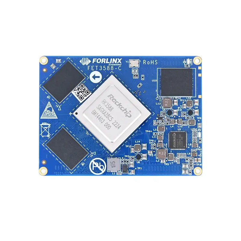

Detailed Guide on MIPI CSI Camera Adaptation and Debugging Methods for Rockchip Platforms
Adapting MIPI CSI cameras on Rockchip platforms typically requires coordinated efforts across multiple components: Sensor driver validation, I²C communication, MIPI D-PHY/CSI-2 link setup, RKCIF, RKISP, IQ file configuration, and V4L2/GStreamer application-layer verification. This article uses the RK3588 platform as the primary example, combining actual device tree code, debugging commands, and common issues to outline a reusable camera adaptation workflow.
1. Why Camera Adaptation Requires More Than Just the Device Tree
In practical projects, whether a camera “outputs images normally” depends not on a single node but on the entire Camera Pipeline. A typical pipeline includes:
  Sensor Driver / I²C Communication
  ↓
  MIPI D-PHY / CSI-2 Receiver
  ↓
  RKCIF (Video Capture)
  ↓
  RKISP (RAW Image Processing, Optional)
  ↓
  RKAIQ / IQ Parameters
  ↓
  V4L2, GStreamer, or Android Camera HAL
Errors in any of these stages may lead to issues such as:
Camera not being detected
No video node generated
Image capture failure
Color abnormalities
Multi-camera synchronization failures Therefore, before starting adaptation, it is crucial to verify documentation and plan the pipeline thoroughly before proceeding with device tree and driver modifications.
2. Preliminary Research: Check if the Sensor Has Existing Adaptation Foundations
When working with a new sensor, first verify whether Rockchip or the current SDK already supports it. Existing drivers and IQ files can significantly reduce adaptation effort.
2.1 Locating the Sensor Driver in the Kernel Source
MIPI CSI cameras are typically configured via I²C register writes. Start by searching in the following directories:
  drivers/media/
  drivers/media/i2c/
For example, to locate drivers for OV13850 or OV13855:
  find drivers/media -iname "*ov13850*"
  grep -R "ov13850" drivers/media/

  find drivers/media -iname "*ov13855*"
  grep -R "ov13855" drivers/media/
If a driver exists, update the device tree configuration; otherwise, you need to port or develop a new driver based on the sensor's datasheet and existing Rockchip sensor templates.
2.2 Checking Platform Support List and Historical Projects
If the driver is not found directly in the kernel, check Rockchip’s camera support list, internal project records, or issue tracking systems. Such resources typically provide: Such resources typically provide:
Whether the sensor has been debugged on the target SoC.
Compatible driver and kernel versions.
Availability of IQ/JSON files.
Reference device tree configurations and known limitations.
If no relevant records exist in official or internal documentation, search in open-source communities like GitHub. However, third-party drivers often require re-evaluating register interfaces, V4L2 subdevice APIs, kernel API changes, and RK Camera Framework compatibility—they cannot be assumed directly usable.
3. Confirming Data Format: Must the Sensor Pass Through RKISP?
Whether RKISP is required depends primarily on the sensor’s output data format. Before adaptation, confirm via datasheet, driver register tables, or existing solutions whether the output is RAW, RGB, or YUV.
3.1 RAW Sensor
If the sensor outputs RAW Bayer data, it generally requires RKISP for processing such as:
Demosaicing
Auto Exposure (AE)
Auto White Balance (AWB)
Auto Focus (AF)
Noise reduction
Color correction Typical pipeline:
RAW Sensor → MIPI D-PHY → MIPI CSI2 → RKCIF → RKISP → Video Node
In such cases, besides the driver and device tree, IQ files matching the sensor, lens, and RKAIQ version are mandatory.
3.2 YUV Sensor or Video Decoder Chip
If the device itself already outputs YUV data—for example, certain YUV sensors, AV video decoder chips or bridge chips—it is possible to capture the YUV data directly from the RKCIF node without passing through the RKISP:
YUV Sensor / Decoder → MIPI CSI2 → RKCIF → Video Node
Note: Bypassing RKISP does not mean skipping MIPI D-PHY, CSI-2, and RKCIF configurations—only RAW image processing and IQ parameter stages are omitted.
4. Key Parameters to Confirm from the Sensor Datasheet
4.1 External Input Clock
Most MIPI CSI sensors use a 24 MHz external reference clock, but this is not universal. For example, TP2855 specifies “Single 27MHz clock operation,” meaning it requires a 27 MHz clock input.
Ensure clock-frequency in the device tree or CRU clock output matches both the chip requirements and driver register configurations.
4.2 MIPI Lane Count
Confirm whether the sensor supports 1, 2, or 4 lanes (or multiple combinations). The data-lanes in the device tree must match:
The actual lanes connected in the hardware schematic.
The lane count configured in the sensor’s registers.
The mode used by the D-PHY and CSI-2 controller.
Example for 2 lanes:
data-lanes = <1 2>;
4.3 Maximum Resolution, Frame Rate, and Bandwidth
Confirm the chip’s maximum resolution, frame rate, and bit depth. For instance, TP2855 supports multiple HD-TVI/analog HD video decoding channels and outputs via a MIPI CSI-2 compliant transmitter, supporting up to 4 lanes.
For instance, TP2855 supports multiple HD-TVI/analog HD video decoding channels and outputs via a MIPI CSI-2 compliant transmitter, supporting up to 4 lanes.
4.4 I²C Address and Hardware Pull-up/Pull-down
Some sensors or decoder chips support multiple I²C slave addresses via address selection pins, enabling multiple identical devices on the same I²C bus. Example: TP2855
The combination of SAD0 and SAD1 pin levels determines multiple I²C addresses.
Figure 1: Example of I²C address selection via SAD0/SAD1 pull-up/pull-down.
In Linux device trees, the reg field typically uses the 7-bit I²C address. During debugging, distinguish between the 7-bit address in datasheets and the 8-bit address (which includes R/W bits).
  cam1_ov13850: cam1_ov13850@10 {
  reg = <0x10>;
  };
5. ISP Architecture for Different Rockchip Platforms
Different SoCs may use varying ISP architectures and Camera Frameworks. Refer to the SDK docs directory for platform-specific Camera/ISP driver guides. Common platform-ISP mappings:
| Platform | ISP Architecture |
| RK3399 / RK3288 / RK3326 / RK1808 | ISP1.x |
| RK3566 / RK3568 | ISP2.1 |
| RK3588 | ISP3.0 |
| RK3562 | ISP3.2 Lite |
Taking the RK3588 as an example, you should focus on referring to the corresponding version of the Rockchip Camera Driver Guide to confirm the D-PHY, CSI2, VICAP/RKCIF, ISP virtual node, and multi-camera resource allocation methods. Different SoCs may have variations in device tree node naming and connection methods; directly copying configurations across platforms is not recommended.
6. RK3588 Multi-Camera Resource and Link Planning
Before configuring the device tree, you should first clarify which D-PHY group, CSI2 controller, RKCIF, and ISP virtual node each camera path uses. The schematic for RK3588 multi-camera support in the source materials is as follows.
Figure 2: RK3588 Multi-Sensor Hardware Resource and Software Link Schematic
6.1 D-PHY Full Mode and Split Mode
The D-PHY resources on the RK3588 can be configured in Full Mode or Split Mode based on the camera’s Lane count. Full Mode is typically used for a single 4-Lane camera.
Split Mode allows the same PHY group to be split into two 2-Lane paths.
Block Diagram Description
Figure 3: RK3588 D-PHY Full/Split Mode Description
Figure 4: RK3588 Multi-Camera Configuration Notes
When configuring, pay attention to the following principles:
Full Mode and its corresponding Split Mode cannot be enabled simultaneously.
Each physical PHY should be connected to a matching CSI2 controller.
Each MIPI CSI2 output should continue to be connected to an independent RKCIF/VICAP node.
When multiple RAW cameras feed into the ISP, appropriate ISP virtual nodes must be allocated for each link.
The data-lanes property in the device tree must be consistent with the Full/Split mode and the actual hardware connections.
6.2 RKCIF/VICAP and ISP Connection Methods
On the RK3588, camera data typically enters VICAP/RKCIF first and is then connected to the ISP via interfaces like sditf. The connection methods can be divided into:
Direct Mode: VICAP data is sent directly to the ISP without passing through DDR, resulting in lower latency. However, this is usually suitable for linear mode and is not ideal for HDR.
DDR Mode: RKCIF first writes data to DDR, and then the ISP reads it. This mode is suitable for scenarios requiring buffering or HDR.
If only one ISP virtual node is configured, it is typically used in linear mode. If multiple related virtual nodes are configured, you need to combine this with the sensor’s HDR output method and the driver documentation.
6.3 Hardware Interface Example
Figure 5: Multi-Camera Interface Hardware Connection Example
7. Device Tree Configuration: Building a Complete Media Pipeline
The following uses the OV13850 on the RK3588 platform as an example, preserving the main device tree configurations from the source materials. In actual projects, modifications should be made based on the board schematic, kernel driver, and camera model, including the I²C bus, GPIO, clocks, Lane count, and node numbering.
Note: The code below is intended to demonstrate the complete link and key configuration items. The compatible strings, GPIO polarity, clock names, and node numbers must align with the actual BSP and driver.
7.1 External Fixed Clocks and RKCIF Base Nodes
  / {
  ext_cam_clk: external-camera-clock {
  compatible = "fixed-clock";
  clock-frequency = <24000000>;
  clock-output-names = "CLK_CAMERA_24MHZ";
  #clock-cells = <0>;
  };
  };

  &rkcif {
  status = "okay";
  };

  &rkcif_mmu {
  status = "okay";
  };
ext_cam_clk defines a fixed 24 MHz clock. The sensor node references it through the clocks and clock-names properties. rkcif and rkcif_mmu enable the camera capture module and its corresponding IOMMU, respectively.
7.2 Enabling MIPI DCPHY, ISP, and ISP MMU
  &mipi_dcphy0 {
  status = "okay";
  };

  &rkisp0 {
  status = "okay";
  };

  &isp0_mmu {
  status = "okay";
  };
mipi_dcphy0 corresponds to the physical layer resource used by the camera. rkisp0 and isp0_mmu are used for RAW image processing. If the sensor outputs YUV directly and does not require ISP processing, the ISP-related connections can be omitted according to the actual link, but the RKCIF configuration must still be set up normally.
7.3 I²C Bus, Lens Driver, and Sensor Node
  &i2c3 {
  status = "okay";
  clock-frequency = <400000>;

  vm149c_0: vm149c@0c {
  compatible = "silicon touch,vm149c";
  status = "okay";
  reg = <0x0c>;
  rockchip,camera-module-index = <0>;
  rockchip,camera-module-facing = "back";
  };

  cam1_ov13850: cam1_ov13850@10 {
  compatible = "ovti,ov13850";
  status = "okay";
  reg = <0x10>;

  clocks = <&ext_cam_clk>;
  clock-names = "xvclk";

  pwdn-gpios = <&extio EXTIO_GPIO_P01 GPIO_ACTIVE_HIGH>;
  reset-gpios = <&extio EXTIO_GPIO_P00 GPIO_ACTIVE_HIGH>;

  rockchip,camera-module-index = <0>;
  rockchip,camera-module-facing = "back";
  rockchip,camera-module-name = "forlinx";
  rockchip,camera-module-lens-name = "default";
  lens-focus = <&vm149c_0>;

  port {
  cam1_ov13850_out: endpoint {
  remote-endpoint = <&mipi_in_0_ucam1>;
  data-lanes = <1 2>;
  };
  };
  };
  };
Key Configuration Items Explanation:
reg: The 7-bit I²C address of the sensor.
clocks / clock-names: The sensor’s external input clock. The name must match the one used by devm_clk_get() in the driver.
pwdn-gpios / reset-gpios: Power-down and reset control. The GPIO polarity must be verified against the schematic and the driver’s timing requirements.
rockchip,camera-module-index: Camera module index. This value must not be arbitrarily duplicated when multiple cameras are used.
camera-module-name / lens-name: Used not only for module information but also to match the IQ (Image Quality) file name.
data-lanes: Indicates the enabled MIPI data lanes (in this example, two lanes).
remote-endpoint: Used to connect the sensor’s output port to the D-PHY input port.
7.4 DCPHY Input/Output Ports
  &csi2_dcphy0 {
  status = "okay";

  ports {
  #address-cells = <1>;
  #size-cells = <0>;

  port@0 {
  reg = <0>;
  #address-cells = <1>;
  #size-cells = <0>;

  mipi_in_0_ucam1: endpoint@1 {
  reg = <1>;
  remote-endpoint = <&cam1_ov13850_out>;
  data-lanes = <1 2>;
  };
  };

  port@1 {
  reg = <1>;
  #address-cells = <1>;
  #size-cells = <0>;

  csidcphy0_out: endpoint@0 {
  reg = <0>;
  remote-endpoint = <&mipi0_csi2_input>;
  };
  };
  };
  };
Port@0 on the DCPHY is used as an input and is connected to the sensor; port@1 is used as an output and is connected to the MIPI CSI2 controller. The data lanes on both the Sensor and DCPHY sides should be aligned.
7.5 MIPI CSI2 Controller
  &mipi0_csi2 {
  status = "okay";

  ports {
  #address-cells = <1>;
  #size-cells = <0>;

  port@0 {
  reg = <0>;
  #address-cells = <1>;
  #size-cells = <0>;

  mipi0_csi2_input: endpoint@1 {
  reg = <1>;
  remote-endpoint = <&csidcphy0_out>;
  };
  };

  port@1 {
  reg = <1>;
  #address-cells = <1>;
  #size-cells = <0>;

  mipi0_csi2_output: endpoint@0 {
  reg = <0>;
  remote-endpoint = <&cif_mipi_lvds0>;
  };
  };
  };
  };
The input of the MIPI CSI2 node is connected to the DCPHY, whilst the output is connected to the RKCIF MIPI/LVDS acquisition node.
7.6 RKCIF to ISP Virtual Node
  &rkcif_mipi_lvds {
  status = "okay";

  port {
  cif_mipi_lvds0: endpoint {
  remote-endpoint = <&mipi0_csi2_output>;
  };
  };
  };

  &rkcif_mipi_lvds_sditf {
  status = "okay";

  port {
  mipi_lvds_sditf: endpoint {
  remote-endpoint = <&isp0_vir0>;
  };
  };
  };

  &rkisp0_vir0 {
  status = "okay";

  port {
  #address-cells = <1>;
  #size-cells = <0>;

  isp0_vir0: endpoint@0 {
  reg = <0>;
  remote-endpoint = <&mipi_lvds_sditf>;
  };
  };
  };
rkcif_mipi_lvds receives the MIPI CSI2 output; rkcif_mipi_lvds_sditf feeds the acquired data into the ISP; rkisp0_vir0 corresponds to a virtual channel of the ISP. In multi-camera configurations, appropriate RKCIF and ISP virtual nodes must be allocated to the different links.
7.7 Checking Whether the Endpoints Are Connected in Pairs
The “remote-endpoint” entries in the device tree must appear in pairs. For example:
  cam1_ov13850_out ↔︎ mipi_in_0_ucam1
  csidcphy0_out ↔︎ mipi0_csi2_input
  mipi0_csi2_output ↔︎ cif_mipi_lvds0
  mipi_lvds_sditf ↔︎ isp0_vir0
If the name of any endpoint pair is incorrect, the node is not enabled, or it is connected to a mismatched controller, the Media Controller topology may become incomplete, ultimately leading to the failure of video node generation or capture.
8. RK3588 Camera Clock Output Configuration
In addition to fixed clock nodes, the RK3588 can also output camera clocks through the CRU and corresponding GPIO multiplexing functions. The source material lists multiple sets of available MIPI camera clock outputs.
Figure 6 RK3588 Camera Clock Output Pins and Optional Frequencies
8.1 Pinctrl Configuration Example
  /* arch/arm64/boot/dts/rockchip/rk3588s-pinctrl.dtsi */

  mipi {
  /omit-if-no-ref/
  mipim0_camera0_clk: mipim0-camera0-clk {
  rockchip,pins =
  /* mipim0_camera0_clk */
  <4 RK_PB1 1 &pcfg_pull_none>;
  };

  /omit-if-no-ref/
  mipim0_camera1_clk: mipim0-camera1-clk {
  rockchip,pins =
  /* mipim0_camera1_clk */
  <1 RK_PB6 2 &pcfg_pull_none>;
  };

  /omit-if-no-ref/
  mipim0_camera2_clk: mipim0-camera2-clk {
  rockchip,pins =
  /* mipim0_camera2_clk */
  <1 RK_PB7 2 &pcfg_pull_none>;
  };

  /omit-if-no-ref/
  mipim0_camera3_clk: mipim0-camera3-clk {
  rockchip,pins =
  /* mipim0_camera3_clk */
  <1 RK_PD6 2 &pcfg_pull_none>;
  };

  /omit-if-no-ref/
  mipim0_camera4_clk: mipim0-camera4-clk {
  rockchip,pins =
  /* mipim0_camera4_clk */
  <1 RK_PD7 2 &pcfg_pull_none>;
  };
  };
8.2 Sensor Node Referencing CRU Clock
  clocks = <&cru CLK_MIPI_CAMARAOUT_M1>;
  clock-names = "xvclk";

  pinctrl-names = "default";
  pinctrl-0 = <&mipim0_camera1_clk>;
The value of clock-names must exactly match the definition in the driver. Even if multiple sensors use 24 MHz, the clock name retrieved by the driver may differ.
9. ISP IQ Files and the RKAIQ Service
Once RAW sensor data enters the RKISP, image quality and 3A functionalities depend on a matching IQ file. If the device tree configuration is correct but the IQ file is missing or version mismatched, the following phenomena may occur: only RAW capture is possible, abnormal colors, abnormal exposure, or even failure of multiple ISP virtual nodes to work simultaneously.
9.1 IQ File Naming Convention
The common IQ file path in the filesystem is:
/etc/iqfiles/
The IQ filename is typically composed of the sensor model, camera-module-name, and camera-module-lens-name. The corresponding OV13850 IQ file can be named:
  rockchip,camera-module-name = "forlinx";
  rockchip,camera-module-lens-name = "default";
The corresponding OV13850 IQ file can be named:
ov13850_forlinx_default.json
Only when the name matches the module information can the RKAIQ automatically load the correct configuration file.
9.2 Checking rkaiq_3A_server
ps -ef | grep 3A
Normally, a process similar to the following should be visible:
  /usr/bin/rkaiq_3A_server
  logger -t rkaiq_3A
If rkaiq_3A_server is not running properly, check the IQ filename, file format, RKAIQ library version, device tree module information, and whether the ISP node is complete.
9.3 Querying the RKAIQ Library Version
strings /usr/lib/librkaiq.so | grep -w AIQ
The output will show version information similar to AIQ v6.0x8.0. IQ file structures may differ across RKAIQ library versions; old version JSON files may not be directly usable with a new SDK.
For instance, IQ files for the same sensor may have compatibility differences between platforms like Linux 5.10.66, Linux 5.10.209, or Linux 6.1, requiring the use of the default IQ file from the corresponding version for regeneration or debugging.
10. Obtaining and Adjusting IQ Files
10.1 Finding IQ Files in the SDK
Search primarily in the following directory:
external/camera_engine_rkaiq/iqfiles/
If the SDK does not contain files for the target sensor, you can further consult Rockchip’s support list, other projects, or IQ resources under the same RKAIQ version.
10.2 Using RKISP Tuner
Rockchip provides the RKISP Tuner tool for configuring and adjusting IQ parameters. Before use, confirm the following:
Target SoC platform.
RKAIQ Library Version.
Default IQ file for the corresponding version.
Sensor operating mode, resolution, and frame rate.
Figure 7 RKISP Tuner Platform and Version Selection Interface
If the version is selected incorrectly, even if the JSON can be read, issues such as incompatible parameter items, service startup failure, or abnormal image effects may occur.
10.3 Limitations of Manual JSON Modification
In the absence of Tuner or a corresponding default IQ file, you can directly edit the JSON, but this method is only suitable for verifying a small number of parameters. If the root cause is version mismatch, comparing against a properly loadable IQ file and migrating parameters item-by-item is required, which is labor-intensive and not recommended as a regular solution.
Typical symptom: Under the same device tree configuration, when calling different virtual nodes of the same RKISP, the first node captures successfully, but the second node reports an error. This type of issue may not be a device tree connection error but rather RKAIQ not functioning properly or missing a matching IQ file.
Figure 8 RK3562 Multi-Camera Link and RKAIQ Configuration Issue Example
11. Common V4L2 and Media Controller Debugging Commands
11.1 Listing All Video Devices
v4l2-ctl --list-devices
Used to confirm registered camera, RKCIF, and ISP video nodes in the system.
11.2 Listing Formats, Resolutions, and Frame Rates Supported by a Node
v4l2-ctl --list-formats-ext -d /dev/video33
If the target format or resolution does not appear in the enumeration results, continue checking the sensor driver mode table, RKCIF/ISP output formats, and Android HAL enumeration requirements.
11.3 Viewing Media Pipeline
media-ctl -p -d /dev/media0
This command prints the entities, pads, and link relationships between Sensor, D-PHY, CSI2, RKCIF, and ISP. It is one of the most important tools for troubleshooting endpoint configuration issues.
11.4 Viewing Each Video Node Name
grep -H '' /sys/class/video4linux/video*/name
Since /dev/videoX numbers can change with configuration, do not judge node purpose solely by number; also check the node name in sysfs.
11.5 Capturing a Single NV12 Frame
  v4l2-ctl -d /dev/video0 \
  --set-fmt-video=width=1920,height=1080,pixelformat=NV12 \
  --stream-mmap=3 \
  --stream-skip=3 \
  --stream-to=./cif.yuv \
  --stream-count=1 \
  --stream-poll
Parameter description:
--set-fmt-video: Sets width, height, and pixel format.
--stream-mmap=3: Uses MMAP method to request buffers.
--stream-skip=3: Skips the first 3 frames to reduce impact from unstable frames during startup.
--stream-to: Saves data to a file.
--stream-count=1: Captures 1 frame.
12. Using GStreamer for Fixed-Point Preview
In a graphical system, GStreamer can be used to output a V4L2 node’s signal to the screen.
12.1 Wayland render-rectangle Method
  gst-launch-1.0 v4l2src device=/dev/video0 ! \
  video/x-raw,format=NV12,width=1920,height=1080,framerate=30/1 ! \
  waylandsink async=false "render-rectangle=<0,0,500,300>"
The four parameters of render-rectangle are: window origin X coordinate, origin Y coordinate, window width, and window height. This example displays a 500×300 preview window in the top-left corner of the screen.
12.2 Using Window Position Parameters
  gst-launch-1.0 v4l2src device=/dev/video0 ! \
  video/x-raw,format=NV12,width=1920,height=1080,framerate=30/1 ! \
  waylandsink window-width=500 window-height=300 \
  window-x=0 window-y=0 async=false
Parameter support may vary across different system images and plugin versions; test accordingly based on the actual environment.
13. Differences Between Buildroot, Ubuntu, and Android Systems
13.1 Buildroot
The Buildroot system is typically more suitable for low-level debugging, allowing separate kernel compilation and image updates. For older RK3588 Linux 5.10.66 kernels, RKCIF nodes might not work correctly with V4L2 capture commands. The source material provides a fix example for the selection logic.
  diff --git a/drivers/media/platform/rockchip/cif/capture.c b/drivers/media/platform/rockchip/cif/capture.c
  index ce479ff27..c0236fc28 100644
  --- a/drivers/media/platform/rockchip/cif/capture.c
  +++ b/drivers/media/platform/rockchip/cif/capture.c
  @@ -5181,9 +5181,7 @@ static int rkcif_g_selection(struct file *file,
  s->r.width = stream->pixm.width;
  s->r.height = stream->pixm.height;
  }
  - }
  -
  - if (s->target == V4L2_SEL_TGT_CROP) {
  + } else if (s->target == V4L2_SEL_TGT_CROP) {
  if (stream->crop_mask & (CROP_SRC_USR_MASK |
  CROP_SRC_SENSOR_MASK)) {
  s->r = stream->crop[CROP_SRC_ACT];
  } else {
  @@ -5192,6 +5190,8 @@ static int rkcif_g_selection(struct file *file,
  s->r.width = stream->pixm.width;
  s->r.height = stream->pixm.height;
  }
  + } else {
  + goto err;
  }

  return ret;
This patch adjusts the judgment logic of rkcif_g_selection() for different selection targets. Higher kernel versions typically already include similar fixes, so before actual use, the current BSP code should be compared to avoid redundant modifications.
13.2 Ubuntu
Ubuntu systems require attention to the differences between the X11 and Wayland display frameworks. Taking the RK3588 Ubuntu 22 environment as an example, if using the Wayland desktop for preview, the following steps are generally required:
Set the screen to single display mode.
Log in with a regular desktop account.
Set the DISPLAY environment variable in the terminal.
Run the GStreamer preview command.
export DISPLAY=:0
If the environment variable, desktop session, or display framework is mismatched, issues such as windows failing to display or color abnormalities may occur.
13.3 Android Camera HAL
Android not only requires the underlying V4L2 node to be available but also demands that the enumeration methods for resolution and frame rate are correctly recognized by the Camera HAL. In older driver versions, it may be necessary to change continuous enumeration to discrete enumeration. Example code from the source material is as follows:
  diff --git a/kernel/drivers/media/platform/rockchip/cif/capture.c b/kernel/drivers/media/platform/rockchip/cif/capture.c
  index 6c0aa7d8b3..62f89e5b89 100644
  --- a/kernel/drivers/media/platform/rockchip/cif/capture.c
  +++ b/kernel/drivers/media/platform/rockchip/cif/capture.c
  @@ -3452,10 +3452,16 @@ static int rkcif_try_fmt_vid_cap_mplane(struct file *file, void *fh,
  return 0;
  }

  +#define USB_CAMERA_TEST
  +
  static int rkcif_enum_framesizes(struct file *file, void *prov,
  struct v4l2_frmsizeenum *fsize)
  {
  +#ifdef USB_CAMERA_TEST
  + struct v4l2_frmsize_discrete *d = &fsize->discrete;
  +#else
  struct v4l2_frmsize_stepwise *s = &fsize->stepwise;
  +#endif
  struct rkcif_stream *stream = video_drvdata(file);
  struct rkcif_device *dev = stream->cifdev;
  struct v4l2_rect input_rect;
  @@ -3474,6 +3480,11 @@ static int rkcif_enum_framesizes(struct file *file, void *prov,
  get_input_fmt(dev->terminal_sensor.sd,
  &input_rect, stream->id, &vc);

  +#ifdef USB_CAMERA_TEST
  + fsize->type = V4L2_FRMSIZE_TYPE_DISCRETE;
  + d->width = input_rect.width;
  + d->height = input_rect.height;
  +#else
  fsize->type = V4L2_FRMSIZE_TYPE_STEPWISE;
  s->min_width = CIF_MIN_WIDTH;
  s->min_height = CIF_MIN_HEIGHT;
  s->max_width = input_rect.width;
  s->max_height = input_rect.height;
  s->step_width = OUTPUT_STEP_WISE;
  s->step_height = OUTPUT_STEP_WISE;
  -
  +#endif
  return 0;
  }

  @@ -3512,6 +3523,11 @@ static int rkcif_enum_frameintervals(struct file *file, void *fh,
  fi.interval.denominator = 30;
  }

  +#ifdef USB_CAMERA_TEST
  + fival->type = V4L2_FRMIVAL_TYPE_DISCRETE;
  + fival->discrete.numerator = fi.interval.numerator;
  + fival->discrete.denominator = fi.interval.denominator;
  +#else
  fival->type = V4L2_FRMIVAL_TYPE_CONTINUOUS;
  fival->stepwise.step.numerator = 1;
  fival->stepwise.step.denominator = 1;
  fival->stepwise.max.numerator = 1;
  fival->stepwise.max.denominator = 1;
  fival->stepwise.min.numerator = fi.interval.numerator;
  fival->stepwise.min.denominator = fi.interval.denominator;
  -
  +#endif
  return 0;
  }
This modification allows RKCIF to report the current input resolution and frame rate as discrete values, making them easier for the Android Camera HAL to recognize.
In newer kernels and Android BSPs, Rockchip has migrated such compatibility logic to device tree properties. For example, in RK3576 Linux 6.1.75 Android 14, you can add the following under the RKCIF node:
  &rkcif {
  status = "okay";
  rockchip,android-usb-camerahal-enable;
  };
Therefore, before modifying the driver, check whether the current BSP already supports this device tree property.
14. Common Issues and Troubleshooting Sequence
For camera issues, it is recommended to troubleshoot in the following order:
Hardware Power Supply and Clock → I²C → Driver Probe → Media Pipeline → RKCIF Image Capture → ISP/RKAIQ → Application Display.
| Phenomenon | Key Checks | Recommended Methods |
| I²C Cannot Detect Sensor | Power supply, RESET/PWDN, MCLK, I²C address | Measure voltage and clock; use i2cdetect; check GPIO polarity. |
| Driver Not Probing | compatible, I²C address, clock, and power supply names | Check dmesg; verify driver match table and device tree. |
| No /dev/videoX | Endpoint link, node status, PHY/CSI2/RKCIF | Use media-ctl -p; check remote-endpoint. |
| RKCIF Visible but Image Capture Fails | Format, resolution, kernel version, Crop/Selection | Check v4l2 enumeration; compare with higher kernel version patches. |
| RAW Capture Works, YUV/ISP Node Fails | ISP virtual node, IQ file, RKAIQ service | Check /etc/iqfiles; inspect rkaiq_3A_server. |
| Color Distortion or Exposure Issues | IQ file matching lens and sensor, RKAIQ version | Use Tuner; verify JSON filename and version. |
| First Stream Works, Second Stream Fails | D-PHY Split/Full, ISP virtual node, IQ file | Check multi-camera resource allocation and 3A service. |
| Android Cannot Recognize | Frame size/frame rate enumeration and Camera HAL properties | Check discrete enumeration or android-usb-camerahal-enable property. |
| Ubuntu Cannot Display | Wayland/X11, DISPLAY, desktop account | export DISPLAY=:0; verify sink plugin and display session. |
14.1 Confirming Hardware Prerequisites
Ensure all power supply voltages for the Sensor are correct.
Verify default levels and release sequence for PWDN and RESET.
Verify default levels and release sequence for PWDN and RESET.
Check MIPI Lane order, count, and impedance design against the schematic.
Check MIPI Lane order, count, and impedance design against the schematic.
14.2 Confirming Driver and Media Pipeline
  dmesg | grep -i camera
  dmesg | grep -i sensor
  dmesg | grep -i ov13850

  media-ctl -p -d /dev/media0
  v4l2-ctl --list-devices
If the Sensor has probed but the Media topology lacks a complete link from the Sensor to RKCIF/ISP, prioritize checking the device tree endpoint rather than modifying the application directly.
14.3 RKCIF vs. ISP Issues
If RAW/YUV data can be captured from the RKCIF node but the ISP output node is abnormal, the issue typically lies with the ISP virtual node, IQ file, or RKAIQ service. If RKCIF itself cannot capture images, return to troubleshooting the Sensor, D-PHY, CSI2, and kernel driver layers.
15. Recommendations for Adaptation Work
Prefer Sensors already supported by Rockchip with existing driver and IQ files in the current BSP.
Before formally modifying code, map out the complete pipeline: Sensor → PHY → CSI2 → RKCIF → ISP.
After modifying the device tree, validate the underlying layer using media-ctl and v4l2-ctl before relying on upper-layer applications.
For multi-camera setups, plan D-PHY Full/Split, Lane count, and ISP virtual nodes in advance.
Ensure IQ files match the Sensor, lens, operating mode, and RKAIQ version.
Before copying patches or JSON files across kernel versions, confirm whether the current BSP already includes the corresponding features.
Conclusion
Adapting MIPI CSI cameras on Rockchip platforms essentially involves establishing a complete imaging pipeline from the hardware Sensor to the application layer. The device tree describes the connections between hardware modules. The Sensor driver initializes the device and outputs the correct data stream. RKCIF handles image capture.RKISP and RKAIQ manage RAW image processing and 3A. V4L2, GStreamer, or Android Camera HAL are used for final validation and application. During debugging, the most effective approach is not to repeatedly modify the device tree through trial and error, but to verify the pipeline step by step:
Confirm power supply, clock, and I²C.
Validate Sensor probe and Media Pipeline.
Verify RKCIF raw data.
Inspect ISP, IQ files, and upper-layer display. This layered method significantly improves the efficiency of camera adaptation and multi-camera issue localization.
Appendix: Quick Reference of Common Commands
  # List video devices
  v4l2-ctl --list-devices

  # List formats supported by a node
  v4l2-ctl --list-formats-ext -d /dev/video33

  # View Media topology
  media-ctl -p -d /dev/media0

  # List video node names
  grep -H '' /sys/class/video4linux/video*/name

  # Check 3A service
  ps -ef | grep 3A

  # Query RKAIQ library version
  strings /usr/lib/librkaiq.so | grep -w AIQ

  # Set Ubuntu display environment
  export DISPLAY=:0