
Implementation of SPI-to-Ethernet Expansion with W5500 on OKMX93xx Linux 6.1.36 Platform
Taking the SPI3 Adaptation of OKMX9352-C Development Board as an Example
In certain industrial control, data acquisition, gateway, and multi-port network device applications, when the number of native Ethernet interfaces of the processor is insufficient to meet the requirements, additional network interfaces can be expanded via the SPI interface. This article, based on the OKMX9352-C development board and the Linux 6.1.36 system, introduces the adaptation process of using the W5500 module to expand a 100M Ethernet port through SPI3. The main steps include kernel driver configuration, device tree modification, hardware connections, driver compilation and loading, and network communication testing.
| Key Points of the Solution: The W5500 module used in this case operates at a logic level of 3.3V. If the SPI pins used are at a 1.8V level, a level conversion circuit is required. According to original test records, this SPI-to-100M Ethernet solution can achieve a maximum speed of approximately 80 Mbps. |
Figure 1: W5500 Network Module Used in Testing
1. Testing Plan
This adaptation was carried out primarily in the following environments:
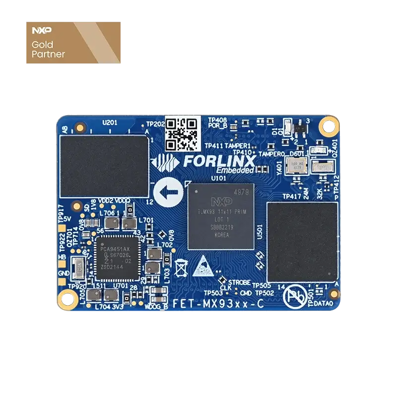
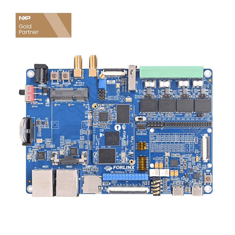
OKMX9352-C Development Board
Linux 6.1.36
LPSPI3 Interface
W5500 Network Module
  OKMX9352-C
  │
  │ SPI3
  ├── SCS
  ├── MISO
  ├── MOSI
  ├── SCLK
  ├── INT
  └── RST
  │
  ↓
  W5500
  │
  ↓
  Ethernet
On the Linux system side, it is necessary to configure the WIZnet-related drivers and add a W5500 node in the device tree.
2. Enabling Linux Kernel Drivers
First, enable WIZnet-related driver support in the Linux Kernel. Navigate to the kernel configuration path:
  Device Drivers
  └── Network device support
      └── Ethernet driver support
Find and enable the following configurations:
  [*] WIZnet devices
  <M> WIZnet W5100 Ethernet support
  <M> WIZnet W5100/W5200/W5500 Ethernet support for SPI mode
In this instance, the relevant functions are compiled as modules. Although the actual hardware used is the W5500, the corresponding driver module name generated by the Linux kernel is:
  w5100.ko
  w5100-spi.ko
3. Modifying the Device Tree
This implementation uses LPSPI3 on the OKMX9352-C to connect to the W5500. Add the W5500 device under the LPSPI3 node. The reference configuration is as follows:
  &lpspi3 {
  fsl,spi-num-chipselects = <1>;
  pinctrl-names = "default", "sleep";
  pinctrl-0 = <&pinctrl_lpspi3>;
  pinctrl-1 = <&pinctrl_lpspi3>;
  cs-gpios = <&gpio2 8 GPIO_ACTIVE_LOW>;
  status = "okay";

  ethernet: w5500@0 {
  compatible = "wiznet,w5500";
  reg = <0>;
  status = "okay";
  pinctrl-names = "default";
  pinctrl-0 = <&pinctrl_w5500>;
  interrupt-parent = <&gpio2>;
  interrupts = <5 IRQ_TYPE_EDGE_FALLING>;
  spi-max-frequency = <15000000>;
  };
  };
Key configuration items include:
compatible = "wiznet,w5500": Specifies that the current SPI device is a W5500.
reg = <0: Corresponds to the SPI chip select.
interrupts = <5 IRQ_TYPE_EDGE_FALLING>: Configures the interrupt trigger mode for the W5500.
spi-max-frequency = <15000000>: The SPI maximum frequency for this test is set to 15 MHz.
4. Configuring SPI Pin Multiplexing
After completing the device node configuration, it is also necessary to configure the pin multiplexing for SPI3. The reference configuration is as follows:
  pinctrl_lpspi3: lpspi3grp {
  fsl,pins = <
  MX93_PAD_GPIO_IO08__GPIO2_IO08 0x3fe
  MX93_PAD_GPIO_IO09__LPSPI3_SIN 0x3fe
  MX93_PAD_GPIO_IO10__LPSPI3_SOUT 0x3fe
  MX93_PAD_GPIO_IO11__LPSPI3_SCK 0x3fe
  >;
  };
At the same time, configure the INT and RST pins on the W5500:
  pinctrl_w5500: w5500grp {
  fsl,pins = <
  MX93_PAD_GPIO_IO04__GPIO2_IO04 0x31e // INT
  MX93_PAD_GPIO_IO05__GPIO2_IO05 0x31e // RST
  >;
  };
| Reset Explanation: According to the original documentation, the W5500 driver defaults to using software reset. Therefore, the RST pin only needs to be ensured to have a pull-up connection. |
5. Hardware Connection
The wiring connections between the W5500 module and the OKMX9352-C are as follows:
| OKMX9352-C | W5500 |
|---|---|
| LPSPI3_PCS0 | SCS |
| LPSPI3_SIN | MISO |
| LPSPI3_SOUT | MOSI |
| LPSPI3_SCK | SCLK |
| GPIO_IO04 | INT |
| GPIO_IO05 | RST |
Level Note: The W5500 logic level is 3.3V. If the SoC’s corresponding SPI pins are at 1.8V, they should not be directly connected. A level conversion circuit must be included in the hardware design.
6. Compiling the Kernel and Drivers
After the Kernel configuration and device tree modifications, recompile the kernel in the OKMX93 Linux SDK:
./build.sh kernel
Upon successful compilation, the main files that need to be updated for this test include:
  OK-MX93-C.dtb
  w5100.ko
  w5100-spi.ko
The development board update method referenced in the test materials is as follows:
  cp /run/media/boot-mmcblk1p1/OK-MX93-C.dtb /run/media/Boot-mmcblk0p1/
  cp /run/media/boot-mmcblk1p1/w5100.ko ./
  cp /run/media/boot-mmcblk1p1/w5100-spi.ko ./
7. Loading the W5500 Driver
After completing the device tree replacement and booting the system, load the W5500 driver modules sequentially:
  insmod w5100.ko
  insmod w5100-spi.ko
After the modules are loaded, execute:
ifconfig -a
If the device tree, SPI communication, and drivers are functioning correctly, you will see a new network interface added to the system. In this test, it is identified as eth2.
eth2: flags=<UP, BROADCAST, RUNNING,MULTICAST,DYNAMIC> mtu 1500
If the network card is not yet active, you can run the following command:
ifconfig eth2 up
8. Configuring IP and Testing Network Communication
After the driver is successfully loaded, configure an IP address for the W5500 network interface:
ifconfig eth2 172.20.2.167
Then perform a Ping test with the specified network card:
ping -I eth2 172.20.2.166
The initial test results indicated that all four data packets were successfully received, demonstrating a packet loss rate of 0 percent. This confirms that the SPI communication, the W5500 driver, the eth2 network interface, and the IP communication link were all established successfully.
  4 packets transmitted, 4 received, 0% packet loss
  rtt min/avg/max/mdev = 0.076/0.089/0.127/0.021 ms
9. Adaptation Process Overview
  Confirm SPI interface and voltage levels
  ↓
  Enable Linux WIZnet driver
  ↓
  Modify LPSPI3 device tree
  ↓
  Configure CS / MISO / MOSI / SCLK
  ↓
  Configure INT / RST
  ↓
  Recompile Kernel and DTB
  ↓
  Update device tree and load driver
  ↓
  System recognizes eth2
  ↓
  Configure IP and perform Ping test
  ↓
  Network communication functioning normally
10. Key Issues to Focus on During Debugging
First, confirm interface voltage levels
W5500 operates at 3.3V logic levels. If the corresponding SoC SPI bank uses 1.8V, a level-shifting circuit must be added.
Driver name is not w5500.ko
The Linux kernel modules for W5500 SPI mode are w5100.ko and w5100-spi.ko.
Pay attention to SPI chip select configuration
In this project, LPSPI3_PCS0 is connected to the SCS of W5500, and configured in the device tree using cs-gpios.
Pay attention to interrupt configuration
The INT pin of W5500 is connected to GPIO_IO04. The hardware connection must match the interrupt description in the device tree.
Confirm whether the network device is created
After loading the driver, use ifconfig -a to verify that eth2 appears before proceeding to IP configuration and ping testing.
11. Summary
This document, based on the OKMX9352-C + Linux 6.1.36 platform, completes the adaptation of expanding an Ethernet interface via LPSPI3 connection to a W5500 module.
The entire process includes:
Kernel driver configuration
Device tree modifications
SPI and interrupt pin configuration
Kernel and DTB compilation
Driver loading
Network communication testing
During testing, after driver loading, the system successfully recognized the newly added eth2 network card. The network card could be brought up normally and performed IP configuration and ping communication with 0% packet loss, indicating that the basic functionality of the SPI-expanded W5500 network interface solution has been validated.
For applications with limited native Ethernet interfaces that require additional network ports, this solution serves as a reference for expanding 100 Mbps Ethernet interfaces via SPI on the OKMX93xx platform.