
Verification of Mechanical Reliability for Embedded Motherboards: Testing for Vibration, Shock, and Crashes
Embedded development boards are frequently subjected to continuous vibration and transient shocks in industrial environments and during long-distance transport. Such physical stresses can easily lead to solder joint fatigue cracking, loose connectors or system crashes.
To ensure the long-term reliability of motherboards under complex working conditions, Forlinx Embedded’s Physical Environment Laboratory has established a three-major mechanical testing system covering vibration, shock and bump. Through standardized limit tests, we identify potential hazards in structures and connectors before delivery, ensuring stable operation after product handover.
Vibration Test
Simulating Transportation and Continuous Operation Conditions to Verify Long-term Vibration Resistance
Test Application Scenarios
This test simulates persistent vibration scenarios including low-frequency jolts during truck transportation, ocean vessel swaying, and long-term high-frequency resonance from motor equipment, to evaluate the long-term fatigue resistance and anti-loosening performance of PCB solder joints, TF card sockets and various types of connectors. The vibration table supports wide-frequency vibration ranging from 2 to 2000Hz, with the conventional sine vibration test interval covering 10 to 500Hz, which can cover vibration sources in the vast majority of industrial and vehicle-mounted transportation scenarios.
At high vibration frequencies, the amplitude is nearly invisible to the naked eye. The equipment can provide a maximum acceleration of 981m/s², equivalent to 100 times the gravitational acceleration. The test is completed independently along the three orthogonal directions of X, Y and Z, to verify the structural tolerance in all dimensions.
Faults Identifiable Through Vibration Testing
Under prolonged continuous vibration conditions, the test can proactively detect on-site high-frequency faults including solder joint fatigue cracking, connector loosening, component resonance desoldering, and system mounting errors.
Standardized Test Procedures
- Test Preparation: Inspect the appearance and full functional status of the sample to confirm the equipment is in good condition; install acceleration sensors, and secure the development board tightly with dedicated tooling fixtures;
- Parameter Configuration: Set the frequency, displacement amplitude, acceleration, sweep cycle and total test duration according to the customer’s actual usage scenarios;
- Three-axis Testing: Turn on the power amplifier and control system, and conduct tests on the X/Y/Z axes in sequence; the sensors collect vibration curves in real time, the device remains powered on throughout the process, and real-time monitoring is carried out to check for abnormalities in each functional port;
- Post-test Re-inspection: Shut down the vibration equipment, check the sample for deformation or component falling off; power on to perform a full set of functional tests to determine if the test result is qualified.
Result Certification
The sample for this test is the Forlinx Embedded OK3506J-C Development Board. After completing the full three-axis vibration test, the prototype shows no damage in appearance and all functions operate normally, so the test result is judged as qualified.
Shock Test
Simulating Instantaneous Violent External Impact to Verify Instantaneous Shock Resistance
Test Application Scenarios
This test targets single sudden high-intensity impact scenarios: equipment drop impact, vehicle emergency brake shock, hard object collision at construction sites, instantaneous collision during equipment installation, etc. Different from the continuous vibration test, this type of test focuses on evaluating the structural strength of the product to withstand instantaneous high-G value shocks.
Faults Identifiable Through Shock Testing
Under single instantaneous impact, the test can proactively detect major structural damages such as cracking and deformation of PCB boards, enclosures and fixing brackets, as well as instantaneous fracture failure of solder joints for chips, capacitors and connectors.
Standardized Test Procedures
The sample is reinforced and fixed with dedicated tooling, the equipment remains continuously powered on, and the status of each interface is detected in real time;
Apply shock pulses in gradients along the positive and negative directions of the X, Y and Z axes; record phenomena such as disconnection, crash and storage abnormality during the entire shock process;
Carry out appearance inspection and full-function retest after the shock is completed, to confirm there is no permanent hardware damage.
Supported Shock Waveforms
Currently supported waveforms include half-sine wave, peak-first sawtooth wave, peak-last sawtooth wave, triangular wave, rectangular wave, trapezoidal wave and bell-shaped wave. The half-sine waveform is shown as follows:
Result Certification
The sample for this demonstration test is the Forlinx Embedded FCU2601 Embedded Control Unit. After completing the full three-axis shock test, the prototype shows no damage in appearance and all functions operate normally, so the test result is judged as qualified.
Bump Test
Simulate repeated collisions caused by stacked packages in logistics scenarios to troubleshoot intermittent contact faults.
Test Application Scenarios
It sits between vibration testing and shock testing, simulating the low-intensity, high-frequency repeated impacts that occur during logistics packing and transfer, as well as cargo stacking and loading/unloading: scenarios including mutual collisions between cargo boxes inside the carriage, and minor continuous collisions during forklift transfer.
Faults Identifiable Through Bump Testing
The test verifies that various connectors will not experience intermittent disconnections under multiple cycles of small-amplitude impacts, eliminating the risk of interface contact failure during device operation.
Standardized Test Procedures
Fix the sample first: The sample is reinforced and secured with dedicated tooling, the device remains continuously powered on, and the status of all interfaces is detected in real time;
Apply impacts next: Impacts are applied in gradients along the positive and negative directions of the X, Y and Z axes; phenomena such as disconnection, system crash and storage abnormalities are recorded throughout the whole process.
Retest for acceptance: After the test is completed, appearance inspection and full-function retest are carried out to confirm there is no permanent hardware damage.
Result Certification
The sample for this test is the Forlinx Embedded FCU2601 Embedded Control Unit. After completing the full three-axis bump test, the prototype shows no damage in appearance and all functions operate normally, so the test result is judged as qualified.
Functional Differences Between Vibration / Shock / Bump Tests
Vibration Test
Targets long-term continuous vibration working conditions, to verify the device’s long-term anti-fatigue and anti-loosening performance.
Shock Test
Targets single sudden violent impacts, to verify the instantaneous overload resistance of structures and connectors.
Bump Test
Targets repeated collisions during logistics transfer, to troubleshoot hidden faults of intermittent poor contact.
The combination of the three tests covers physical risks across the full lifecycle of embedded devices. It can reproduce faults such as solder joint falling off and peripheral disconnection in vehicle-mounted, rail transit and industrial equipment scenarios in advance, providing a strong basis for optimizing hardware structures and coping with real complex working conditions.
Coverage of Full Set of Mechanical Test Products
Industrial equipment, vehicle-mounted equipment, mobile robots and other products that are permanently in complex vibration environments will suffer huge losses once hardware failures occur. The full set of strict vibration, shock and bump tests can greatly reduce the on-site operation and maintenance failure rate, ensuring stable operation of equipment for several years without interruption.
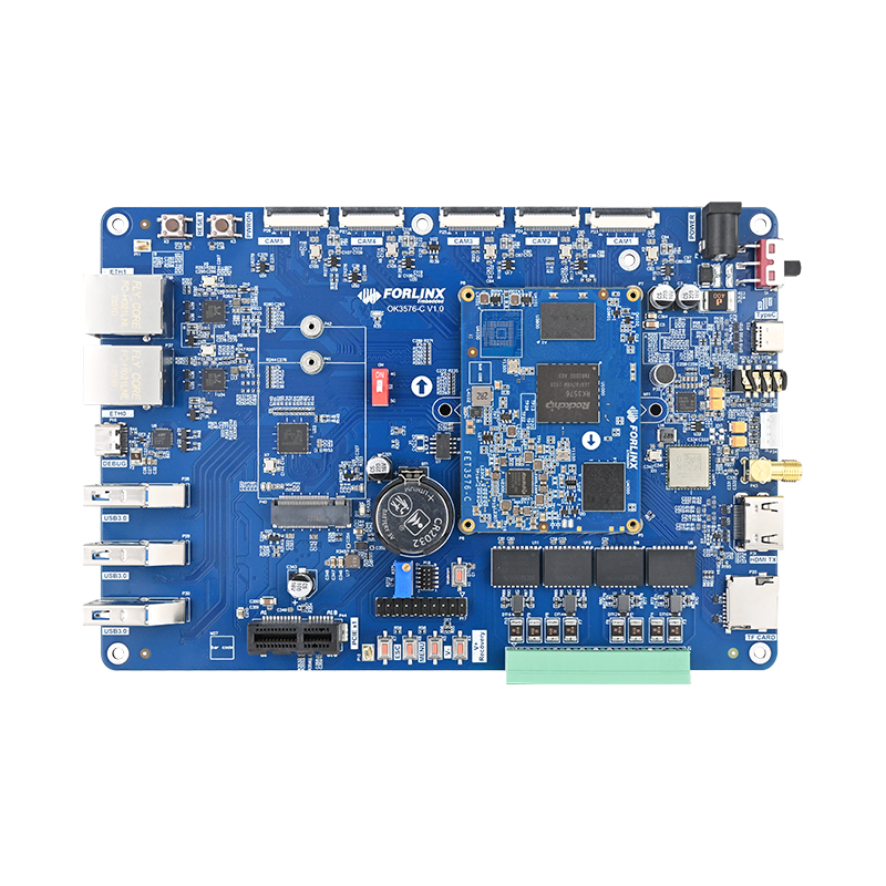
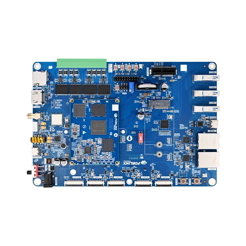
Forlinx Embedded multiple development boards, including the OK3588-C Development Board, OK3576-C Development Board, OK3568-C Development Board, OK3568-UP4 Development Board, OK3562J-C Development Board, OK3506J-C Development Board, OK3506J-S Development Board, OK536-C Development Board, and OKA40i-C Development Board, have passed the full set of mechanical reliability tests. The full set of mechanical tests will be carried out on the rest of the product lines in the follow-up, with standardized execution of test procedures and output of standardized test reports, to continuously guarantee the reliable operation of products under complex working conditions.
Conclusion
In the physical environment laboratory of Forlinx Embedded, every startup of the vibration table, shock table and bump table is a strict check on product hardware reliability. The rigorous mechanical tests of vibration, shock and bump are key verification methods before products move from the ideal laboratory environment to complex outdoor actual working conditions.
Vibration, shock and bump tests are core indicators for Forlinx Embedded products to move from the laboratory to harsh industrial sites. In addition to mechanical tests, we also take environmental reliability tests such as high and low temperature cycling, salt spray and drop tests as standard quality control procedures.
Stable and reliable hardware comes from rigorous data and sufficient verification. Forlinx Embedded will continue to implement high-standard physical and environmental tests, output standardized test reports, and provide solid data support for the operation of customer equipment in scenarios such as vehicle-mounted, industrial control and edge computing.