SoM FET5718-C Applied in AVM and ADAS Solutions
1. Overview
1) What is ADAS and AVM
ADAS is short for Advanced Driving Assistant System, a system to help the driver in the driving process. When designed with a safe Human-Machine Interface, they should increase car safety and more generally road safety.It's developed to automate, adapt and enhance vehicle system for safety and better driving.
Visual related ADAS can much enhance driving safety by equipping vehicles with front, rear and side cameras and also ECU. Popular applications including lane departure warning(LDW), high-beam/ low beam (HB/ LB) adjustment, traffic signal recognition(TSR), parking-assist, rear view/ around view, anti-collision, and so on.
2) Cameras in ADAS
A. Front camera
Camera is used for video processing in ADAS, which can help to enhance driving safety by provide necessary traffic information,such as LDS, LKA, HB/ LB and TSR. Image sensor of front black& white camera will transfer video frame to dual-core MCU expanded by DSP to do image processing, other software related requirements, such as relevant physical communication interface, power, optional DRAM and lower cost embedded flash are also needed.
B. Rear camera
Rear cameras can be used for doing native video analysis to detect objects and pedestrians. Further more, they are available for full native image processing and graphic overplot creating. The cameras are able to do distance measurement and trigger brake intervention. All of these are helful in improving car backing safety.
C. Around visual parking assistant system
Multiple around visual cameras are used for image collecting around the car, and the images will be played on screen in form of virtual top views. Visual angle will move with wheel path to collect images around the car.Generally, an advanced system is equiped with LVDS, fast Ethernet and other economical and efficient links, and 4 to 5 HDR 1.0MP cameras. To take video compacting to reduce requisite communication band width and lower lining standard (eg. non-blocking twisted pair or coaxial cable)
2. How make the solution possible by SoM FET5718-C
A complete ADAS consists of processor, analog components and sernsors. TI processors have a powerful advantage in DSP. ADAS series processors are developed from OMAP. This AM5718 is a processor belongs to Sitara series SoC which integrates with a single Cortex-A15 core@ 1.5GHz, a DSP of C66X@ 750MHz, two dual-core M4@ 213MHz and two dual-core PRUs@ 200MHz, has good performance in 2D, 3D and hardware video codec.
1) Front/ rear/ around cameras expanding solution
A. DS90UB964-Q1 from TI is a multi-functional camera hub which can take FPD-Link III interface to expand 4 saperate cameras to collect video data. When it works with DS90UB913A/913Q, the processor can receive data from a 1.0 MP camera sensor, and can support 720p/800p/960p@ 30Hz or 60Hz FPS, which is used in ADAS applications, such as around visual system, camera mornitoring system, sensor fusion and security mornitoring system.
B. DS90UB913Q serializer and DS90UB914Q deserializer strength the FPD-Link III automiative chipsets related product group.This serializer/ deserializer chipset provides camera modules with precise video and data interface without any software related cost and simpler lining, which is favorable to ADAS solution providers to lower power consumption, reduce cost and lighten the weight. System-level serializer/ deserializer enhanced functions will speed up the camera security system promotion in midrange and entry-level auto market segments. The chipset could be widely used in applications, such as auto front cameras for anti-collision or recognition of traffice signals and padestrian; rear cameras for protection of tailstock. Here below is a solution for visual around cameras.
2) HD interface (scalable for dual-display)
SoM FET5718-C can support up to 3x LCD and HDMI interfaces with resolution up to 1920x 1080@ 60Hz, both resistive and capacitive touching are supported. Dual-display combination of LCD and HDMI is supported with sync or async visions frames. It supports single-channel playback of multi-channel video records and sync playback of 4 external cameras on saperate screens. Meanwhile, smart rear-view mirror function is also scable.
3) Video processing and codec
Two dual-core Cortex-M4 IPU1 and IPU2 are available in AM5718, IPU2 is used for IVA video codec, below forms are all supported
Video Decode: H264, MPEG4, MPEG2, and VC1
Video Encode: H264, and MPEG4
Image Decode: MJPEG
Image Encode: MJPEG
H264 can compact storage of multiple cameras at the same time. The storage system could be expanded by high-capacity external eMMC.
High definition voice playing system can support voice playing in preority and composite multi-voice playing, which combine alarm, navigation and entertainment all in one.
4) Powerful DSP
SoM FET5718-C is integrated with a DSP@ 750MHz and PRU@ 100MHz, which could be used for LWD, TSR, physical objects dection. OpenCV, OpenCL and OpenGL deomos are all kindly provided, which take it a great convenience to users' development.
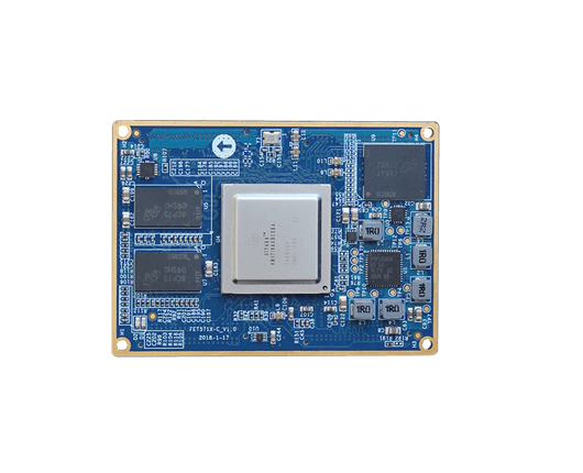
3. Overview of SoM FET5718-C
| Overview of FET5718-C System on Module | |||
|---|---|---|---|
| CPU | TI Sitara AM5718 | ||
| Architecture | Cortex-A15-1.5GHz | DSP-C66X-750MHZ | 2xDual Cortex-M4-213MHz |
| 2xDual-Core PRU-200MHz | PowerVR SGX544 3D GPU | Vivante GC320 2D GPU | |
| RAM | 1GB DDR3L | Flash/ Storage | 8GB eMMC |
| Dimensions | 50*70mm | Pakcage | board to board connector |
| PMU | TPS659162RGZR | Voltage Input | 5V |
| Working Temp Width | -40℃~+85℃ | RH | 10-90%RH non-condensing |
| OS | Linux4.9.41+ QT5.6+Wayland | ||
| FET5718-C System on Module Features | ||
|---|---|---|
| Peripheral | QTY | Spec. |
| LCD | ≤3 | GB888 24-bit |
| HDMI | 1 |
HDMI 1.4a, 1080P@60Hz; 36-bit RGB display; HDCP 1.4 encryption; Deep color mode (10-bit, 12-bit color depth are both supported by pixel clock of 148.5MHz) |
| CAMERA | ≤4 |
2x 8-bit DVP, up to 5.0MP
2x 8/ 16/ 24-bit DVP
|
| MIPI CSI-2 | 2 |
CSI-2_PHY1: 1 clock lane+ 4 data lane
CSI2_PHY1: 1 clock lane+ 1 data lane
CSI2_PHY1: 1 clock lane+ 4 data lane CSI2_PHY1: 1 clock lane+2 data lane |
| SD/MMC/SDIO | ≤4 |
1-bit or 4-bit transferring mode is supported by SD and SDIO card with UHS-I SDR104 mode (up to 104MB/s)
SD/ MMC/ SDIO1: 4-bit data
SD/ MMC/ SDIO2: 8-bit data (used as eMMC on SoM)
SD/ MMC/ SDIO3: 8-bit data
SD/ MMC/ SDIO4: 4-bit data |
| IIC | ≤5 |
IIC1/ 2: up to 400Kbps, standard OD
IIC3/ 4/ 5: up to 3.4Mbps, analogy OD
|
| HDQ1W | ≤1 |
Support TI/ Benchmarq HDQ master device function
Comply with Dallas 1-Wire protocol |
| UART | ≤10 |
can support 5/ 6/ 7/ 8 data bits, parity bit, 1, 1.5, 2 stop bits UART1: full serial interface is supported UART3: IrDA 1.4, CIR are supported others are standard interface |
| SPI | ≤4 |
up to 4x SPI, each with up to 4 master channel |
| QSPI | ≤1 |
work as master mode only
6 signal pins |
| McASP | ≤8 |
supports 8-ch audio at most
McASP1/2: up to 16 separate TX/ RX channel
McASP3-8: up to 4 separate TX/ RX channel |
| USB3.0 | ≤1 |
super speed USB3.0 Dual-Role-Device, Host is supported |
| USB2.0 | 1 |
high-speed USB 2.0 Dual-Role-Device, Host is supported |
| SATA | 1 | SATA Gen2 |
| PCIe | ≤2 |
PCI Express 3.0 subsystem, with 2x 5-Gbps channel
1x Dual-channel interface with GEN2 standard, 2x Single-channel intgerface with Gen2 standard |
| CAN | ≤2 |
two CAN controller at most, complys with CAN2.0 protocol |
| Ethernet | ≤2 |
3-port gigabit ethernet switch subsystem provides ethernet packet communication and can be configured as an ethernet switch. It provides two network ports and available for RGMII/ RMII/ MII interface, 10M/ 100M/ 1000M adaptive |
| PWMSS | ≤3 |
supports up to 3x PWMSS, each is available for:
eHRPWM: 16-bit timer, up to 2 separate PWM output
eCAP: 32-bit timer, one channel is special for input capture pin
eQEP: rotating decode unit |
| JTAG | supported | standard IEEE1149.1 |
| KeyPad Port | supported | 9*9 keyboard |
| GPMC | 1 |
8-bit/ 16-bit data bus width
up to 28-bit address bus
up to 8-bit chip selection bus |
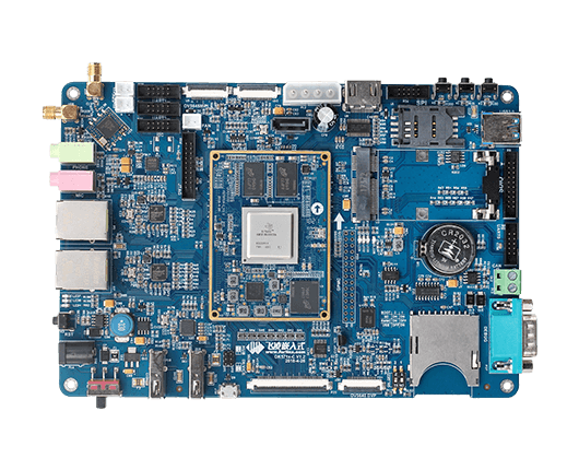
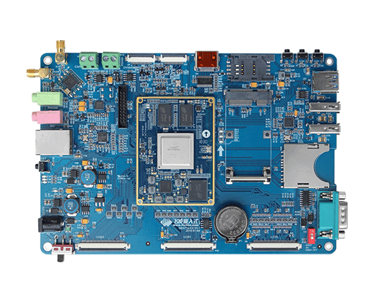
4. OK5718-C Development Board
| OK5718-C Single Board Features | ||
|---|---|---|
| Peripheral | QTY | Spec. |
| LCD | 1 |
RGB 888, supports reolution up to 1920*1080 (60Hz) |
| HDMI | 1 |
HDMI V1.4, up to 1080P 60FPS |
| CAMERA | 3 |
8-bit DVP OV5640, MIPI OV5640, MIPI OV5645 |
| Audio | 1 | 1*MIC, 1*Phone, 2*Speaker |
| USB Host | 2 |
expended by HUB, USB 2.0 (up to 480Mbps) |
| USB3.0 | 1 | up to 5Gbps |
| USB Device | 1 | multiplexed with one USB Host |
| Ethernet | 2 | 10/100/1000Mbps auto-negotiation, RJ45 connector |
| WiFi | 1 |
RL-UM02WBS-8723BU-V1.2 IEEE 802.11b/g/n 1T1R WLAN and Bluetooth |
| Bluetooth | 1 | |
| SD Card | 1 | compatible with SD, SDHC and SDXC(UHS-I) |
| SDIO | 1 |
drawn out by 20-pin heards with pitch of 2mm, multiplexed with SD card |
| LED | 2 |
for user's definition |
| GPMC | 1 | GPMC |
| QSPI | 1 | on-board 256Mb QSPI NOR FLASH |
| SPI | 1 | |
| IIC | 2 | |
| CAN | 1 | CAN 2.0B |
| UART | 3 |
UART0 and UART1 are 5-wire serial interface, UART2 is a 3-wire interface, all are with 3.3V, each up to 5.0Mbps |
| UART Debug | 1 |
RS232, DB9 connector |
| JTAG Debug | 1 | |
| HDQ | 1 |
single line interface, on-board DS18B20 |
| SATA | 1 |
SATA2, on-board 4pin D type power input connector |
| mini PCIe | 1 | can support 3G, 4G wireless module |