Power Architecture Resolution - OKA40i-C Development Board
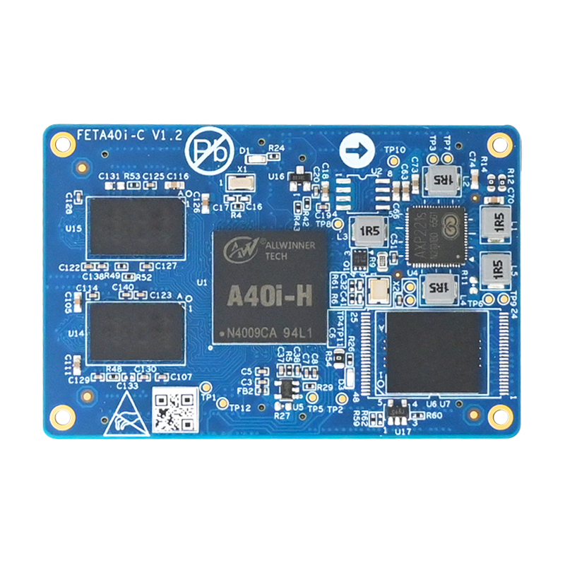
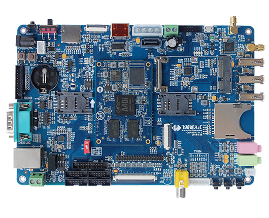
Recently, Forlinx Embedded officially launched the first domestic industrial-grade platform OKA40i-C development board. Based on the all-purpose industrial-grade A40i Cortex-A7 quad-core processor, the main frequency is up to 1.2GHz, the internal integration of the Mali400 MP2 GPU graphics processor, the interface is rich, in the energy ratio, cost-effective performance and so on is outstanding. This article is intended to do a detailed combing of the power architecture of the OKA40i-C board.
OKA40i-C board in the Forlinx A40i family supports three power supply modes: ACIN (powered by power adapter), VBAT (powered by lithium battery), and USB VBUS (USB powered).
These three power supplies can be entered into the PMIC within the A40i core board at the same time or individually, and are managed by the PMIC chip AXP221S, which selects the appropriate power distribution method according to the external power supply status.
The following power management scenarios are excerpted from PMIC's manual:
- ■ When only connected to lithium batteries, no external power input, the use of lithium battery power supply,;
- ■ When connected to an external power supply (VBUS or ACIN), priority use of external power supply power supply;
- ■ When the battery is connected, the external power supply is removed, immediately seamless transfer to lithium battery power supply;
- ■ When VBUS and ACIN are connected at the same time, priority use of ACIN power supply, and charging lithium battery VBUS co-supply;
- ■ In this way, when the ACIN drive capacity is insufficient, the VBUS path will be opened in due course to achieve ACIN/VBUS common power supply;
- ■ If the drive capacity is still insufficient, the charging current will be reduced to 0, which will be replenished with battery power.
Next, take a look at how the three power supply methods of the board are implemented.
1, ACIN (power adapter power supply)
The DC 5V of the external power adapter is input by P23 or P37 to the end board, after the overpressure protection circuit ACIN power supply for the A40i core board, the A40i core board power is completed will output VCC_3V3 as the enable signal on U19, VCC5V for the base plate device power supply.
2, VBAT (lithium battery power)
The user can connect lithium batteries to the P21 socket on the A40i board. The TS pin is either the battery temperature sensor input or the external ADC input, and the TS pin has a 12bit ADC that monitors the battery temperature.
The diagram of the lithium battery-powered circuit is as follows:
A. The AXP221 integrates an adaptive charger that automatically controls the charging cycle, and the built-in safety clock automatically stops charging without processor intervention. The charging current can be automatically adjusted according to the power consumption of the system, with battery detection, trickle charging and activation, and the built-in temperature detection circuitry automatically reduces the charging current when the temperature is too high or too low.
B. VTH/VTL is set at high and low temperature thresholds, respectively. The PMIC sends a constant current on the TS pin, which flows through the thermistor, to obtain a detection voltage, and the PMIC emits the appropriate IRQ or pauses charging by measuring the voltage value and comparing it with the set value. If the battery does not have a thermistor, the TS pin can be grounded, and the battery temperature monitoring function is automatically disabled.
C.When the external power supply is connected, the AXP221 first determines whether the external power supply can be used for charging, and when the external power supply is available and the charging function is turned on, the AXP221 automatically starts the charging process, issuing IRQ to host, indicating that the charging process begins. At the same time, the CHGLED pin output is low and can drive the external LED to indicate the charging status, and the A40i base plate uses LED10 to indicate the state of charge.
The following is a diagram of the voltage current of the charging process:
VTRGT is the charging target voltage, which can be set by register and defaults to 4.2V.
VRCH, Auto Recharge Voltage, VRCH - VTRGT - 0.1V.
Lithium batteries supply power to the A40i core board, A40i core board PMIC output VCC_3V3 and PS voltage to the A40i base plate, using the MT3608 chip boot circuit to obtain 5V voltage, the maximum output current of 1A.
When powered by a lithium battery, you need to press and hold the switch key to power on.
3, USB VBUS power supply
The user can supply power directly to the A40i core board through the Micro USB interface of the base plate, the supply voltage is 5V, because the PMIC's USB_VBUS pin is limited power capacity, it is not recommended to use it as the main power supply, to avoid power supply capacity is insufficient, the core board will repeatedly power off and restart.