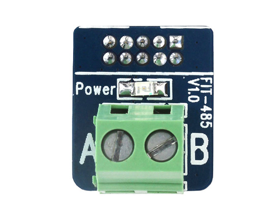
What are Affecting RS485 Communication?
Many customers react to 485 in practical applications, there will be a variety of problems, and the cause of the problem is often easy to ignore the point.
In practical application, in addition to connecting 485 two differential lines, will affect the 485 communication reasons there are a few points, the small editor in the following article to expand the explanation.
01
Since the 485 signal uses a pair of differential signals, the data cable is preferably made up of twisted pairs and is grounded with a shield on the outside to connect the 485 devices in the 485 network and reliably ground at one point.
02
The 485 bus must be grounded. In many technical documents, it is mentioned that the 485 bus must be grounded, but there is no detailed proposal on how to ground. Strictly speaking, the 485 bus must be grounded reliably at a single point. Single point is the entire 485 bus can only have one point ground, not multiple points ground, because it is grounded because the ground wire (generally shielded wire as ground line) voltage is consistent, to prevent common mode interference, if multi-point ground is counterproductive. Reliable grounding when the entire 485 line of ground must have good contact, so as to ensure voltage consistency, because in the actual construction, in order to facilitate wiring, the wire cut into multiple segments and reconnect, but did not make a good connection to the shielding line, so that its ground line is divided into multiple segments, voltage can not be consistent, resulting in common mode interference.
03
To minimize the distance between 485 nodes and trunks in the 485 bus, it is generally recommended that the 485 bus adopt a hand-in-hand bus topology. The star structure produces a reflective signal that affects the 485 communication mass. If the distance of the 485 node from the 485 bus trunk must be required during construction, the 485 repeater is used.
04
The maximum transmission distance of the 485 is approximately 1219 meters and the maximum transmission rate is 10Mbps. The length of the balanced twisted pair is inversely proportional to the transmission rate, and at a rate below 100Kbps, it is possible to use the specified maximum cable length. Maximum rate transfers can only be obtained at a short distance. The maximum transmission rate of a typical 100-meter long twisted pair is only 1Mbps. The RS-485 requires two final resistors, and the impedance requirement is equal to the characteristic impedance of the transmission cable. The terminal resistor can be switched off during short transmissions. The final resistance is connected to the 485 bus at both ends of the transmission bus with the extension of the transmission distance, resulting in echo reflected signal, if the transmission distance of the 485 bus exceeds 100 meters, it is recommended to end the terminal resistance of 120 ohms at the beginning and end of 485 communication at the time of construction.
The connection of the 120 ohm resistor:
05
The number of nodes of 485 is mainly based on the "receiver input impedance". According to the regulations, the input impedance of the standard RS-485 interface is ≥12k, and the corresponding number of standard drive nodes is 32. To accommodate the communication of more nodes, some chips have input impedances designed to be 1/2 load (≥24kω), 1/4 load (≥48kω), or even 1/8 load (≥96kω), and the corresponding number of nodes can be increased to 64, 128, and 256.
Factors affecting the load capacity of the 485 bus: communication distance, wire quality, Baud rate, converter power supply capacity, lightning protection of 485 equipment, 485 chip selection.
If there are more 485 devices on the 485 bus, it is recommended to use a 485 converter with power supply, passive 485 converter due to theft from the serial port, power supply capacity is not enough, load capacity is not enough. Selecting good wire, if possible with the lowest possible Baud rate, and selecting a 485 chip with high load capacity, can increase the load capacity of the 485 bus. The lightning-proof tube in the mine protection of the 485 equipment absorbs voltage, resulting in a decrease in the load capacity of the 485 bus, and removing the lightning protection can improve the load capacity of the 485 bus.


