Application of GPIO Interface for Forlinx OKMX9352-C EVK
01 Multiplexing GPIO
1.1 Adoption of the Iomux Method
1.SD2_DATA01 is used as GPIO.
First look in OKMX93-linux-kernel/arch/arm64/boot/dts/freescale/imx93-pinfunc.h
The specific parameters here are not described anymore. Please check the corresponding registers in the imx93RM_RevD_alpha_customer.pdf manual.
2.The new multiplexed gpio pins in iomux in the device tree are as follows:
Device tree: OKMX93-linux-sdk/OKMX93-linux-kernel/arch/arm64/boot/dts/freescale/OK-MX93-C.dts
3.Add pinctrl_gpio1 pin-multiplexing configuration
Also search for the MX93_PAD_SD2_DATA1 pin name in the device tree to see if it is multiplexed into other functions elsewhere.
We can see that this pin is multiplexed into the USDHC2 function. Please search for pinctrl_usdhc2 to block the USDHC2 function.
4.Compile the device tree. Replace the device tree and re-burn it.
5.View all gpio settings
root@ok-mx93:~# gpiodetect
gpiochip0 [43810080.gpio] (32 lines)
gpiochip1 [43820080.gpio] (32 lines)
gpiochip2 [43830080.gpio] (32 lines)
gpiochip3 [47400080.gpio] (32 lines)
6.We can see from the device tree pin configuration that the corresponding GPIO is gpio@43820080 in the device tree, i.e. gpiochip1.
Specific correspondence:
7.We can use the following command to check which GPIOs are currently occupied in the system.
root@ok-mx93:~# gpioinfo 1
line	0:	unnamed	unused	input	active-high
line	1:	unnamed	unused	input	active-high
line	2:	unnamed	unused	input	active-high
line	3:	unnamed	unused	input	active-high
line	4:	unnamed	unused	output	active-high
line	5:	unnamed	unused	input	active-high
line	6:	unnamed	unused	input	active-high
line	7:	unnamed "regulator-usdhc2" output active-high [used]
line	8:	unnamed	unused	input	active-high
line	9:	unnamed	unused	input	active-high
line	10:	unnamed	unused	input	active-high
line	11:	unnamed	unused	input	active-high
line	12:	unnamed	unused	input	active-high
line	13:	unnamed	unused	input	active-high
line	14:	unnamed	unused	input	active-high
line	15:	unnamed	unused	input	active-high
line	16:	unnamed	unused	input	active-high
line	17:	unnamed	unused	input	active-high
line	18:	unnamed	unused	input	active-high
line	19:	unnamed	unused	input	active-high
line	20:	unnamed	unused	input	active-high
line	21:	unnamed	unused	input	active-high
line	22:	unnamed	unused	input	active-high
line	23:	unnamed	unused	input	active-high
line	24:	unnamed	unused	output	active-high
line	25:	unnamed	unused	output	active-high
line	26:	unnamed	unused	input	active-high
line	27:	unnamed	"key1"	input	active-low [used]
line	28:	unnamed	unused	input	active-high
line	29:	unnamed	unused	input	active-high
line	30:	unnamed	unused	input	active-high
line	31:	unnamed	unused	input	active-high
8.Output modes
We can use the following command to set the GPIO to high level. Measuring high with a multi-meter indicates a successful GPIO test.
root@ok-mx93:~# gpioset gpiochip1 4=1
We can use the following command to set the GPIO to low level. Measuring low with a multi-meter indicates a successful GPIO test.
root@ok-mx93:~# gpioset gpiochip1 4=0
Look at gpioinfo, we can see that line4 is in the output state.
root@ok-mx93:~# gpioinfo 1
gpiochip1 - 32 lines:
........
line 4: unnamed unused output active-high
.......
9.Input modes
We can use the following command to set the GPIO to input mode and read the current GPIO level status.
root@ok-mx93:~# gpioget gpiochip1 4
0
Look at gpioinfo,we can see that line4 is in the input state.
root@ok-mx93:~# gpioinfo 1
gpiochip1 - 32 lines:
........
line 4: unnamed unused input active-high
.......
10.Interrupt mode
We can use the following commands to set GPIO interrupt monitoring
root@ok-mx93:~# gpiomon gpiochip1 4
Pin grounding
root@ok-mx93:~# event: RISING EDGE offset: 4 timestamp: [ 1506.329434716]
Disconnect grounding
root@ok-mx93:~# event: FALLING EDGE offset: 4 timestamp: [ 1506.329421425]
Look at gpioinfo, we can see that line4 is in the input state.
root@ok-mx93:~# gpioinfo 1
gpiochip1 - 32 lines:
........
line 4: unnamed unused input active-high
.......
1.2 Libgpiod Application Examples
Currently
imx93 uses the linux 5.15.52 kernel system. The sysfs GPIO interface (/sys/class/gpio), which previously operated gpio, has been deprecated, and its replacement is the GPIO character device API Libgpiod.
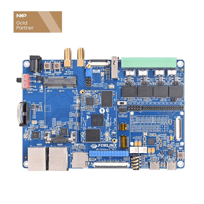
The following is an example of operating the keys (K1) and LEDs (D6) on the
EVK.
1.Modify the device tree
Path:OKMX93-linux-sdk/OKMX93-linux-kernel/arch/arm64/boot/dts/freescale/OK-MX93-C.dts
The default led-1 and keys nodes are first blocked to avoid conflicts,in the following form:
Add the gpio_key node below:
Modify pinctrl_gpio_key to add multiplexing of led pins:
The pins used for buttons are: MX93_PAD_CCM_CLKO2__GPIO3_IO27 LED
The pins used for LEDs are: MX93_PAD_CCM_CLKO3__GPIO4_IO28
Save and exit and recompile the device tree.
After compiling, re-burn OK-MX93-C.dtb
1. Compile the test source code
Copy gpiotest.c, gpio-toggle.c, and lib.tar.bz2 from the Libgpiod test source directory to the development environment.
Extract lib.tar.bz2 to this directory, the gpiod.h file and the libgpiod library will be used for compilation.
Example 1: Cyclic control of LED on and off at 1s intervals
Example 1: Cyclic control of LED on and off at 1s intervals
(1) Set environment variables (note the space after the point)
(2) Cross-compilation
(3) Copy the executable file gpio-toggle to the development board.
(4) Execute and see that the LED (D6) lights up for 1s and goes out for 1s.
Input parameters 2 and 28 are: gpiochip2 line28
Example 2: Press the key to control the LED on and off, and the status will be flipped every time you press the key. Cross-compile gpio-test.c
(1) Set environment variables (note the space after the point)
(2) Cross-compilation
(3) Copy the executable file gpio-test to the development board.
(4) Execute, we can see that every time we press a key, the LED status is flipped once.
Input parameter 1. 27 is: gpiochip1 line27
2.28 for: gpiochip2 line28
02 Extended GPIO
The PCAL6524 is a 24-bit general-purpose I/O expander with i2c interface. Specific description can refer to the "NXP1-PCAL6524HE.pdf". Development board is not welded PCAL6524 by default, if we want to realize this program, the hardware needs to be welded on this module.
In the following test, the PCAL6524 is connected to the i2c3 and the GPIO_IO1 is used for the interrupt pin (if other pins are used as interrupts, we can adjust it accordingly). Configuration and test methods are as follows:
Path:
OKMX93-linux-sdk/OKMX93-linux-kernel/arch/arm64/boot/dts/freescale/OK-MX93-C.dts
1.Add the pcal6524 node under i2c3:
2.Add pinctrl_pcal6524 under the &iomuxc node:
3.Block the previous pin multiplexing to avoid conflicts:
4.Compile Device Tree Replace the device tree and re-burn it.
5.Gpiodetect command to view GPIO devices
We can see the extra gpiochip4, 24 lines. Refer to the "Multiplexing GPIOs" section for the test methods.


