How to Configure NXP i.MX9352's GPIO?
In this article, we may deeply learn how to process the GPIO of i.MX9 family new member- i.MX9352, and it’s similarities and differences with i.MX6ULL.
▊ Hardware Principle Analysis
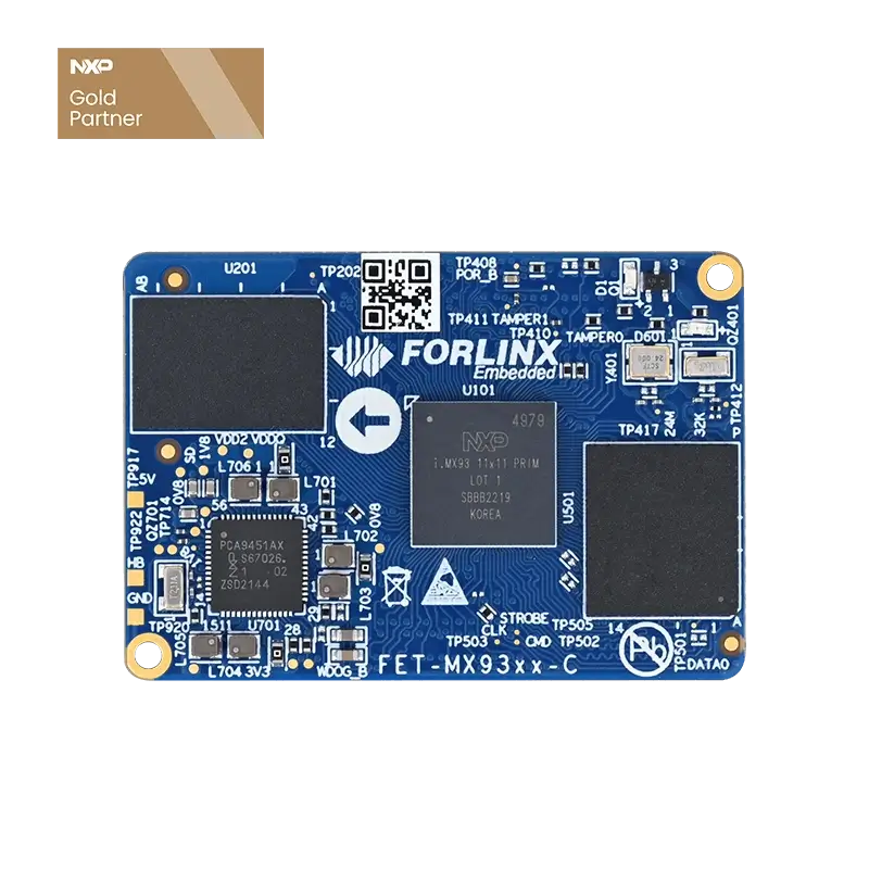
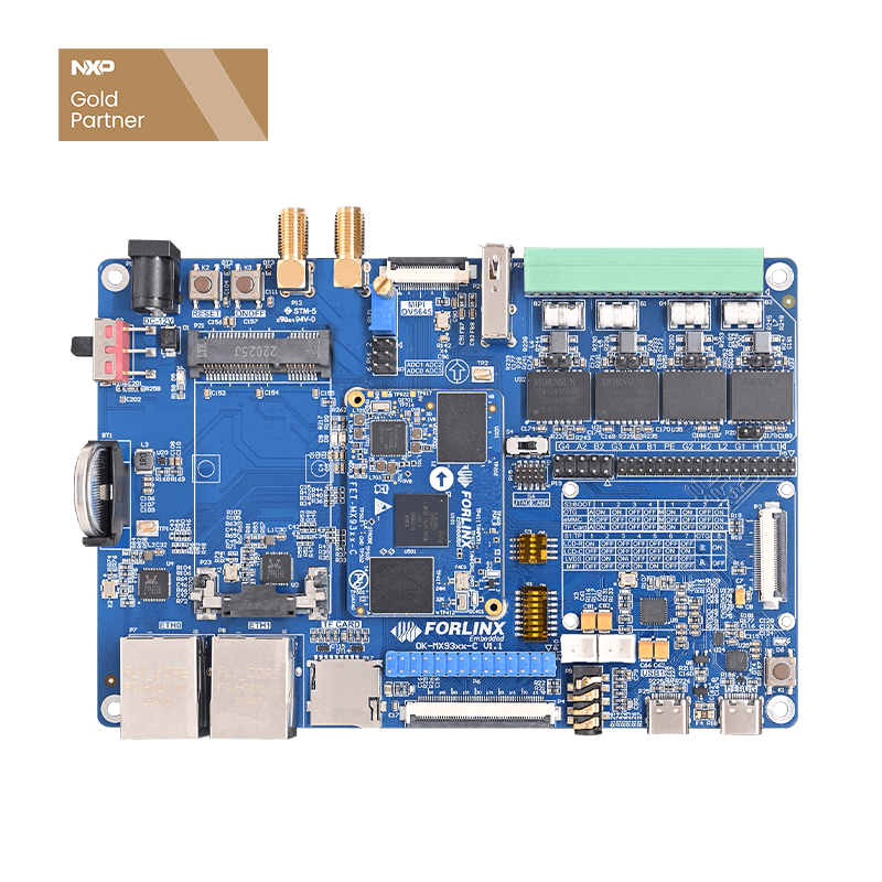
Let’s take LED light and the button as an example. Refer to the SoM diagram, we can see there is one LED light controlled by MX93_PAD_CCM_CLKO4. Because this GPIO ‘s electrical level is 1.8V, it isn’t directly connected to the LED on the carrier board. But in another way, GPIO control one MOSFET, then MOSFET control LED light-- when GPIO electrical level is high, the MOS is connected and LED light on; when GPIO electrical level is low, MOS is disconnected and LED light off.
▊ DTS(Device Tree) Pin Alternate Function
Open Forlinx Embedded OK-MX9352-C DTS:
OKMX93-linux-kernel/arch/arm64/boot/dts/freescale/OK-MX93-C.dts
Create a new set of pin alternates under iomuxc node, and the two GPIOs are LED light D6 and button K1 on the carrier board.
Next, create a new GPIO node as follows:
Annotate LED and KEY parts to avoid alternate conflict:
Compile DTS after Save & Exit
Runtime Environment Variables:
forlinx@ubuntu:~/ok-mx93/OKMX93-linux-sdk$ . environment-setup-aarch64-toolchain
Compile DTS Seperatelly:
forlinx@ubuntu:~/ok-mx93/OKMX93-linux-sdk/OKMX93-linux-kernel$ make ARCH=arm64 CROSS_COMPILE=aarch64-poky-linux- dtbs
After compilation, update the DTS separately. First, insert the USB drive into the virtual machine and copy the generated DTS file to the USB drive:
forlinx@ubuntu:~/ok-mx93/OKMX93-linux-sdk/OKMX93-linux-kernel$ cp arch/arm64/boot/dts/freescale/OK-MX93-C.dtb /media/forlinx/2075-A0A7/
Copy the generated dtb file to the OK-MX9352-C SoM with USB drive and replace it with: /run/media/Boot-mmcblk0p1/OK-MX93-C.dtb
root@ok-mx93:/run/media/Boot-mmcblk0p1# cp /run/media/sda/OK-MX93-C.dtb ./
Restart OK-MX9352-C SoM
▊ Execute Command to Test It
The GPIO’s operation method of OKMX6ULL-S SoM is achieved by files under/sys/class/gpio. But there is a new Lingpiod method for OK-MX9352-C, and the former operation method based on sysfs can’t be supported any more.
Libgpiod is a character device. GPIO visits control by character device(for example:/dev/gpiodchip0).OK-MX9352-C has four sets of GPIO, and GPIO device files can be checked under /dev.
Libgpiod has two using methods: shell terminal and C library. This chapter introduces shell terminal, and next chapter will introduce c library.
3.1 gpiodetect
Check all GPIO devices.
Above gpiochip0- gpiochip4 match with GPIO1- GPIO4 in the DTS respectively. However, it’s not in the order one-to-one, which is caused by the issue of the corresponding register address order. So how does goiochip0 match with the DTS? We can open the dtsi file in the device tree,
path:OKMX93-linux-kernel/arch/arm64/boot/dts/freescale/imx93.dtsi
forlinx@ubuntu:~/ok-mx93/OKMX93-linux-sdk$ vi OKMX93-linux-kernel/arch/arm64/boot/dts/freescale/imx93.dtsi
We can see register address of GPIO3: gpio@43820080, which corresponds to gpiochip1 , and GPIO4 corresponds to gpiochip2.
Followings are other GPIO’s corresponding relationship, please refer.
3.2 gpioinfo
From 3.1, we can see LED light corresponds to GPIO4--gpiochip2;the button corresponds to GPIO3--gpiochip1. List pin status of gpiochip2 controller:
3.3 gpioset
It’s used for setting GPIO electrical level. 2 for gpiochip2--GPIO4, 28 for GPIO pin, when we set GPIO as 1, D6 on carrier board lights.
3.4 gpioget
It’s used for obtaining GPIO pin status. For example, the button corresponds to GPIO3-27--gpiochip1 27, when it’s unpressed, the button status is 1 and when it’s pressed, the button status is 0.
3.5 gpiomon
It’s used for monitoring GPIO change status. Still take the button as an example, when press the button:
▊ Libgpiod Library
Libgpiod is c library and tool used for interacting with Linux GPIO. Linux official implements in Libgpiod function since Linux 4.8.
In the Linux 5.15 kernel version installed on the OK-MX9352-C SoM, the sysfs for GPIO operation is no longer supported. Compared to sysfs, Libgpiod is more reliable and has more functions, such as the ability to read and write multiple GPIO values at once.
4.1 Source Code Obtaining
If we want to cross-compile an application on a PC that can run on SoM, the library files linked during cross-compilation should be consistent with those on SoM. We can directly copy the libraries on the SoM to the development environment for use. Library file on the SoM:
From above Figure, we can see Libgpiod library version is libgpiod.so.2.2.2, and the software is linked to libgpiod.so.2.
In the OK-MX9352-C materials provided by Folinx Embedded, the required library files, header files, and related routines have been packaged for users to use directly. The data path is: user profile/application notes/OK-MX9352-C-GPIO interface_ Linux application notes/Libgpiod testing source code.You may consult on-line customer service to obtain information.
4.2 Compile Test Demo
Copy gpiotest.c、gpio-toggle.c、lib.tar.bz2 uner Libgpiod test source directory to the development environment:
Extract lib.tar.bz2 into this directory, and the gpiod. h file and Libgpiod library file will be used during compilation:
Example 1: Cycle control LED on and off, with a time interval of 1s.
gpio-toggle.c
Cross-compile gpio-toggle.c
Set environment variables(Note: There is space after it)
Cross-compile
Copy the executable file gpio toggle to the SoM and execute it. We can see the LED (D6) light is on for 1 second and off for 1 second. The input parameters 2 and 28 are: gpiochip2 line28.
Example 2: Press the button to control the LED (on & off), and it’s status take change every time you press it.
gpio-toggle.c
Cross-compile gpio-toggle.c
Set environment variables(Note: There is space after it)
Cross-compile
Copy the executable file gpio toggle to OK-MX9352-C SoM and execute it. We can see the the LED status take change every time press it. The input parameters 1 and 27 are: gpiochip2 line28.
That’s the GPIO configuration process for OK-MX9352-C SBC.