M Core SPI Master-Slave Mode Communication of i.MX8M Plus Evaluation Kit
SPI (Serial Peripheral Interface) is a low-cost, easy-to-use interface protocol with full-duplex, high-speed, and simple communication features, and is widely used in communication between microcontrollers and peripheral chips. When the SPI interface is used as the master mode, Flash memory, AD sampling chip, real-time clock RTC, LCD display, audio chip and various sensors can be connected.
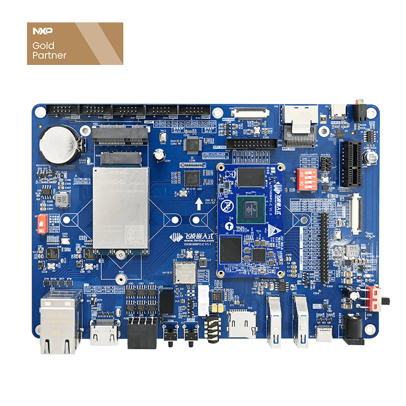
The communication between multiple SPI devices must be controlled by the master device (Master). The OKMX8MP-C development board is designed based on the NXP i.MX8M Plus multi-core heterogeneous processor. Its M core has 1 channel of SPI, so In order to realize the mutual communication of SPI, we need two SPI master-slave devices of the OKMX8MP-C development board to communicate.
The implementation of communication between M-core SPI is as follows:
SPI master mode
1. SPI initialization
SPI initialization mainly includes initialization of the bus clock, pins and corresponding registers. details as follows:
(1)SPI bus clock: Now multiply the SPI bus frequency to 800MHz, and then divide it by 10 to 80MHz.
CLOCK_SetRootMux(kCLOCK_RootEcspi2, kCLOCK_EcspiRootmuxSysPll1); //SPI2 bus clock uses PLL1-800MHz
CLOCK_SetRootDivider(kCLOCK_RootEcspi2, 2U, 5U); //The frequency division factor is 2*5=10, set the SPI2 bus clock to 80MHz
(2)Pin Configuration: Select the four pins of SPI2.
IOMUXC_SetPinMux(IOMUXC_ECSPI2_MISO_ECSPI2_MISO, 0U);  // SPI2-MISO
IOMUXC_SetPinMux(IOMUXC_ECSPI2_MOSI_ECSPI2_MOSI, 0U);  // SPI2-MOSI
IOMUXC_SetPinMux(IOMUXC_ECSPI2_SCLK_ECSPI2_SCLK, 0U);  // SPI2-SCLK
IOMUXC_SetPinMux(IOMUXC_ECSPI2_SS0_ECSPI2_SS0, 0U);    // SPI2-SSO
(3)SPI rate: set the rate to 500K.
#define TRANSFER_BAUDRATE 500000U //rate 500K
(4)Data length selection:8bit.
config->burstLength = 8; // Data length 8bit
(5)Four modes to choose: The four combinations of CPOL and CPHA are the four modes of SPI.
config->clockInactiveState    = kECSPI_ClockInactiveStateLow;   // Clock SCL: low level when active, high level when idle
config->dataLineInactiveState = kECSPI_DataLineInactiveStateLow;// Data MOSI&MISO: low level when active, high level when idle
config->chipSelectActiveState = kECSPI_ChipSelectActiveStateLow;// chip select SS: low level selected, high level invalid
config->polarity = kECSPI_PolarityActiveHigh; // Clock signal polarity, that is, if CPOL is 0, SCLK is active at high level (low level when idle), and at 1, SCLK is active at low level (high level when idle) ).
config->phase = kECSPI_ClockPhaseFirstEdge; // Clock phase, that is, if CPHA is 0, the first transition edge (rising or falling edge) of the serial clock collects data, and if it is 1, the second transition edge of the serial clock (rising or falling edge) to acquire data.
(6)Master mode selection: Set the SPI master mode.
config->channelConfig.channelMode = kECSPI_Master; // Master mode
(7)Channel selection: One SPI has four hardware chip selection signals, each chip selection signal is a hardware channel, this program selects channel 0.
config->channel = kECSPI_Channel0; // channel 0
(8)Turn off the self-loopback: If the self-loopback is turned on, then the SPI data will be looped back in the chip and will not go to the external pins. The interference of the external terminals can be eliminated during program debugging, but in real applications, the self-loopback needs to be turned off. Send and receive data from external pins.
Config->enableLoopBack = false; // No loopback, use external pins
2. SPI transceiver process
We named the two OKMX8MP-C development boards as development board 1 and development board 2 respectively, and adopted the SPI interface of development board 1 as the master mode to enable sending and receiving interrupts; the SPI interface of development board 2 as slave mode and enabled Transceiver interruption.
The SPI master sends 64 bytes of data, and the SPI slave returns the data after receiving it. After receiving the returned information, the SPI master compares whether the received and sent data are consistent, and outputs the comparison result. If they are consistent, the current transmission is over, waiting for any key to be input to start the next transmission.
(1)SPI sending data: EXAMPLE_ECSPI_MASTER_BASEADDR is represented as SPI2, g_m_handle is the SPI instance, including the sending and receiving interrupt and its callback function, and masterXfer is the 64-byte data to be sent.
ECSPI_MasterTransferNonBlocking(EXAMPLE_ECSPI_MASTER_BASEADDR, &g_m_handle, &masterXfer); // Send data in master mode interrupt mode
(2)SPI receiving data: The sending and receiving of the SPI bus are controlled by the master mode, so the process of the receiving function is consistent with the sending.
(3)Receive and send data comparison:
for (i = 0U; i < TRANSFER_SIZE; i++) { if (masterTxData[i] != masterRxData[i]) { errorCount++; } }
SPI slave mode
1. SPI initialization
The SPI slave mode initialization should be consistent with the master mode, except that the working mode is set to slave mode, other settings are the same. Master-slave mode selection: Set SPI to slave mode.
config->channelConfig.channelMode = kECSPI_Slave; //slave mode
2. SPI transceiver process
The SPI interface of the development board 2 adopts the slave mode, and the interrupt of sending and receiving is enabled.
The SPI enters the waiting state from entering the receiving state. After the chip selection is valid, the data is obtained through the receiving interrupt, and the information is returned, and the receiving state is entered again.
(1)SPI receiving data: EXAMPLE_ECSPI_SLAVE_BASEADDR is represented as SPI2, g_m_handle is an SPI instance, including sending and receiving interrupts and their callback functions, and slaveXfer stores the received data.
ECSPI_SlaveTransferNonBlocking(EXAMPLE_ECSPI_SLAVE_BASEADDR, &g_s_handle, &slaveXfer); //Receive data in slave mode interrupt mode
(2)SPI sends data: The sending and receiving of the SPI bus are controlled by the master mode, so the process of receiving the function is consistent with sending.
A Nuclear Modification
If SPI2 is reserved in the A-core device tree, the kernel parses the device tree and generates the device file spidev1.0 under /dev. In this way, after the M core is running, the A core will re-initialize the SPI2, causing the M core SPI function to be abnormal, so it is necessary to remove the control of the A core on the SPI.
1. Modify the device tree
&ecspi2 {
    #address-cells =;
    #size-cells =;
    fsl,spi-num-chipselects =;
    pinctrl-names = "default";
    pinctrl-0 = <&pinctrl_ecspi2 &pinctrl_ecspi2_cs>;
    cs-gpios = <&gpio5 13 GPIO_ACTIVE_LOW>;
    status = "okay";
    spidev1: spi@0 {
        reg =;
        compatible = "rohm,dh2228fv";
        spi-max-frequency =;
    };
};
pinctrl_ecspi2: ecspi2grp {
        fsl,pins = < MX8MP_IOMUXC_ECSPI2_SCLK__ECSPI2_SCLK 0x82 MX8MP_IOMUXC_ECSPI2_MOSI__ECSPI2_MOSI 0x82 MX8MP_IOMUXC_ECSPI2_MISO__ECSPI2_MISO 0x82 >;
};
pinctrl_ecspi2_cs: ecspi2cs {
    fsl,pins = < MX8MP_IOMUXC_ECSPI2_SS0__GPIO5_IO13 0x40000 >;
};
(2) Compile and generate a new kernel image Image and device tree OK8MP-C.dtb.
(3) Copy the generated OK8MP-C.dtb and Image to the development board /run/media/mmcblk2p1/ directory, enter the sync command, and restart the development board.
(4) Enter ls /dev to check and find that there is no SPI2 device file spidev1.0.
Program Verification
1. Hardware connection
Use DuPont lines to connect the SPIs of the two OKMX8MP-C development boards one by one.
The line sequence is as follows:
(1)In the device tree OK8MP-C.dts, delete the information about the SPI2 device node.
|
Development board 1-SPI master mode |
Development board 2-SPI slave mode |
||
|---|---|---|---|
|
Pin name |
Development kit position |
Pin name |
Development kit position |
|
MISO |
P40-10 |
MISO |
P40-10 |
|
MOSI |
P40-8 |
MOSI |
P40-8 |
|
SCK |
P40-1 |
P40-1 |
P40-8 |
|
SS0 |
P40-3 |
P40-3 |
P40-8 |
|
GND |
P40-4/P40-7 |
GND |
P40-8 |
2. M core program
Modify the uboot environment variable to set the M core to start automatically, and at the same time, the M core program forlinx_m7_tcm_firmware.bin
Put it in the /run/media/mmcblk2p1/ directory.
Note that the SPI master mode program must be placed on the development board 1, and the SPI slave mode program must be placed on the development board 2.
3. Practical Testing
(1) The development board 2 is powered on first, the M core program is started, and after the SPI initialization is completed, it enters the receiving waiting state;
(2) After the development board 1 is powered on, the M core program starts, and after the SPI initialization is completed, 64 bytes of data are actively sent;
(3) The SPI of the development board 2 receives data, prints the received data through the serial port, and sends the received data again;
(4) The SPI of the development board 1 receives the returned information and prints the received data through the serial port. Compare with the sent data and output the result.
(5) At this time, enter any key on the debugging serial port of the development board 1 to start a new round of SPI sending and receiving process.


