Master the Complete Process of Reading and Writing Files on Storage Devices at the U-Boot Stage of the RK3588 Development Board in 10 Minutes
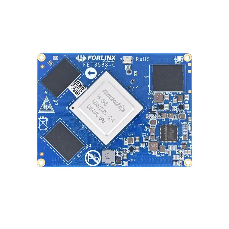
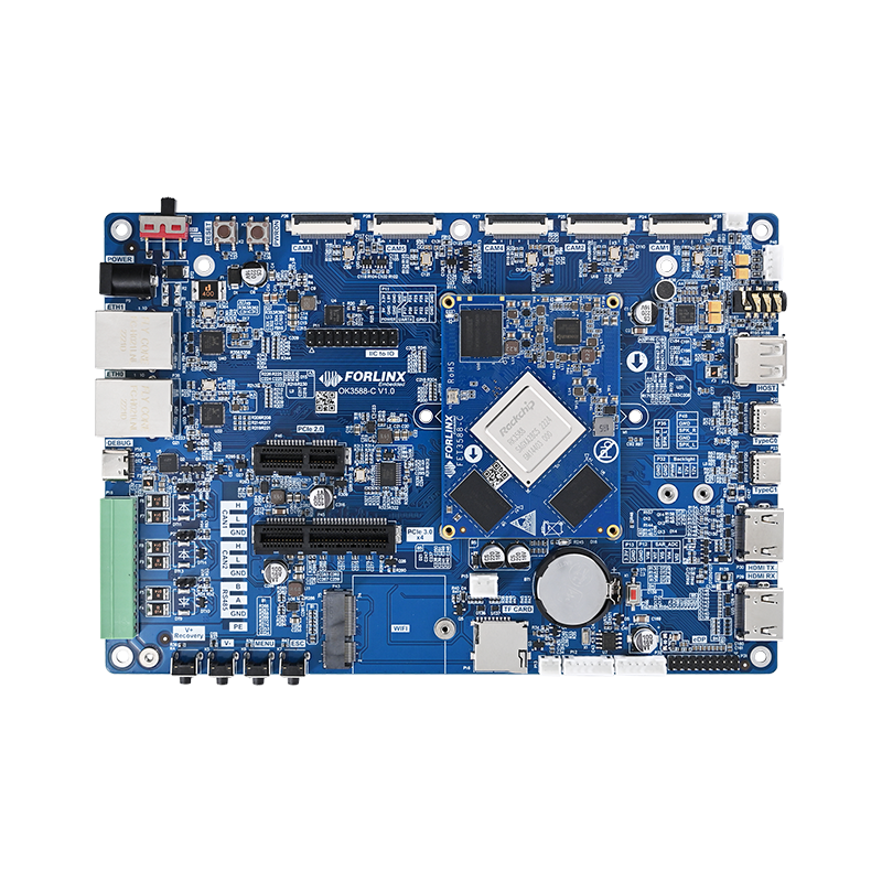
The Forlinx OK3588-C development board is built based on a flagship processor that utilizes an advanced 8nm manufacturing process and adopts a big.LITTLE architecture, featuring four Cortex-A76 cores and four Cortex-A55 cores. It not only features a triple-core NPU with 6 TOPS computing power and 8K ultra-high-definition processing capabilities, but also provides a stable and reliable hardware foundation for storage device debugging through rich hardware designs such as dual independent MMC controllers and multi-specification USB interfaces.
This article outlines standardized methods for accessing the contents of various storage devices (eMMC, TF cards, USB flash drives) during the U-Boot console stage of the RK3588 development board. While the initialization subsystems of various storage devices differ, unified read and write operations can be performed through the U-Boot console, making it ideal for development, debugging, and system verification scenarios.
I. Enter the U-Boot Console
The U-Boot for the Forlinx RK3588 development board has been extensively customized and optimized. By default, there is a reasonable boot delay configured. During the U-Boot startup process, you can interrupt this countdown and enter the interactive console by pressing the Spacebar or Ctrl + C before the automatic startup completes.
The operation interface and an example are as follows:
Hit key to stop autoboot('Spacebar'): 0
0:Exit to console
1:Reboot
2:Display type
=>
Prompt: If you fail to press the key in time, U - Boot will continuethe automatic startup (loading the kernel). You need to restart thedevelopment board and try again.
II. Reading and Writing Files on MMCDevices (EMMC/TF Cards)
The RK3588 development board features dual MMC controllers in its hardware, which correspond to the EMMC and TF card interfaces. It is fully compatible with the EMMC 5.1 specification and the SD 3.0 protocol. The board supports the HS400 high-speed transmission mode and allows for both 8-bit and 4-bit data bus widths. This design provides hardware support for the parallel operation of storage devices. Reading and writing files on MMC devices requires following a four-step process of ''identification → switching → querying → operating''.
The specific steps are as follows:
1. View MMC Controllers
Use the ''mmc list'' command to view the initialized MMC controllers (pre - defined by the device tree, usually 0 corresponds to EMMC and 1 corresponds to the TF card) and confirm whether the devices are recognized:
=> mmc list // View the currently initialized MMC controllers
mmc@fe2c0000: 1
mmc@fe2e0000: 0 (eMMC)Device 'mmc@fe2c0000': seq 1 is in use by
'mmc@fe2c0000'
mmc@fe2c0000: 1Device 'mmc@fe2e0000': seq 0 is in use by
'mmc@fe2e0000'
mmc@fe2e0000: 0
=》
2. Switch MMC Devices
Use the''mmc dev <device number>''command to switch to the target device. The device number corresponds to the controller serial number queried in the previous step:
=> mmc dev 0 // Switch to EMMC
switch to partitions #0, OK
mmc0(part 0) is current device
=> mmc dev 1 // Switch to TF card
switch to partitions #0, OK
mmc0(part 0) is current device
3. View MMC Device Information
After switching the device, use the mmc info command to view the detailed device parameters (capacity, bus width, interface version, etc.).
Examples of EMMC and TF card information are as follows:
Example of EMMC device information:
=> mmc info //EMMC device information
Device: mmc@fe2e0000
Manufacturer ID: 15
OEM: 100
Name: CJTD4
Timing Interface: HS400 Enhanced Strobe
Tran Speed: 200000000
Rd Block Len: 512
MMC version 5.1
High Capacity: Yes
Capacity: 58.2 GiB
Bus Width: 8-bit DDR
Erase Group Size: 512 KiB
HC WP Group Size: 8 MiB
User Capacity: 58.2 GiB WRREL
Boot Capacity: 4 MiB ENH
RPMB Capacity: 4 MiB ENH
Examples of TF card device information:
=> mmc info //TF device information
Device: mmc@fe2c0000
Manufacturer ID: 3
OEM: 5344
Name: SL16G
Timing Interface: Legacy
Tran Speed: 52000000
Rd Block Len: 512
SD version 3.0
High Capacity: Yes
Capacity: 14.8 GiB
Bus Width: 4-bit
Erase Group Size: 512 Bytes
4. View MMC Device Information
Use the MMC part command to view the device partition table (take EMMC as an example, the partition type is EFI), and obtain key information such as the partition name and the start/end address:
=> mmc part
Partition Map for MMC device 0 -- Partition <a href="https://www.forlinx.com/product/rk3399-99.html">Type</a>: EFI
Part Start LBA End LBA Name
Attributes
Type GUID
Partition GUID
1 0x00004000 0x00005fff "<a href="https://www.forlinx.com/article-new-c22/223.html">uboot</a>"
attrs: 0x0000000000000000
type: da7a0000-0000-400e-8000-214900006be8
guid: ae050000-0000-417a-8000-728a000054cf
2 0x00006000 0x00007fff "misc"
.. (omitting some partitions)..
6 0x00078000 0x01c77fff "rootfs" // The rootfs partition to be operated in the example
...
5. View the file system content
Use theext4ls <device type> <device number:partition number>command to view the directory structure of the specified partition (Example: the rootfs partition, which is the 6th partition of the EMMC):
=> ext4ls mmc 0:6
<DIR> 4096 .
<DIR> 4096 ..
<DIR> 16384 lost+found
<SYM> 7 bin
<DIR> 4096 boot
<DIR> 4096 dev
…(Some system directories are omitted)…
<DIR> 4096 home // The parent directory where the target file is located
...
6. Read the file content (Take Hello.txt as an example)
To read the/home/forlinx/Hello.txtfile in the rootfs partition, you need to follow four steps: ''Confirm existence → Select memory address → Load the file → View the content''.
Confirm the file existence:Verify the validity of the target file path usingext4ls:
=> ext4ls mmc 0:6 home/forlinx
<DIR> 4096 .
<DIR> 4096 ..
14 Hello.txt // Target file (size: 14 bytes)
<strong>Determine the available memory address</strong>: Use bdinfo to view the memory distribution and select a safe DDR area.
=> bdinfo
arch_number = 0x00000000
boot_params = 0x00000000
DRAM bank = 0x00000000 // System reserved area, not recommended for use
-> start = 0x00200000
-> size = 0x08200000
DRAM bank = 0x00000001 // Secure availability zone
-> start = 0x09400000
-> size = 0xE6C00000
…(Other hardware information is omitted)…
Warning: Do not use the system -reserved memory (such as DRAM bank 0), otherwise, it may cause the U -Boot to crash or data corruption.
Load the file into memory: Useext4loadto load the file to the specified memory address.
=> ext4load mmc 0:6 0xA0000000 /home/forlinx/Hello.txt 14 bytes
read in 5 ms (2 KiB/s)
View the file content in memory: Use md.b <address> <length>to read the memory data.
=> md.b 0xA0000000 0x10 a0000000: 48 69 2c 20 46 4f 52 4c 49 4e 58
21 21 0a ff fe Hi, FORLINX!!...
7. Modify the file content (You need to enable ext4write)
Important: The ext4write command is disabled by default in U-Boot (to prevent accidental operations). You need to enable it in the U-Boot source code configuration first.
After enabling the function, two modification methods aresupported:
(1)Replacement-style modification (Load an external file tooverwrite):
// Assume that the modified file has been loaded into memory at
0xA0000000
=> ext4write mmc 0:6 0xA0000000 /home/forlinx/Hello.txt 0xe // 0xe
= 14 bytes (file size)
(2)Directly modify the memory data and then write:
// 1. Modify the memory byte by byte (starting from address 0xA0000000):
=> mm.b 0xA0000000
A0000000: 48 ? //This means the current value at address 0xA0000000 is 0x48 (ASCII 'H').
// You can enter a new hexadecimal value and then press Enter.
// For example, change "Hi, FORLINX!!" to "Hi!\n".
=> mw.b 0xA0000000 0x48 // 1st byte: 'H'.
=> mw.b 0xA0000001 0x69 // 2nd byte: 'I'.
=> mw.b 0xA0000002 0x21 // 3rd byte: '!'
=> mw.b 0xA0000003 0x0A // 4th byte: newline character '\n'
=> md.b 0xA0000000 0x20
// 2. Verify the modification result
=> md.b 0xA0000000 0x20
a0000000: 48 69 21 0a 46 4f 52 4c 49 4e 58 21 21 0a ff fe Hi!.FORLINX!!...
// 3. Write to the file system
=> ext4write mmc 0:6 0xA0000000 /home/forlinx/Hello.txt 0xe
III. Reading Files from USB Devices(such as USB flash drives)
USB devices are external storage. Please initialize the USB subsystem first to recognize them. The steps are as follows:
1. Initialize the USB subsystem:
Use the usb start command to start the USB controller and scan for devices. After successful recognition, the number of storage devices will be displayed.
=> usb start
starting USB...
Bus usb@fc000000: usb maximum-speed not found
Register 2000140 NbrPorts 2
Starting the controller
USB XHCI 1.10
…(USB initialization logs are omitted)…
scanning usb for storage devices... 1 Storage Device(s) found // One USB flash drive is recognized
Tip: If the device is not recognized, check the USB flash drive connection (it is recommended to plug it into a USB 2.0 port) or re-execute the usb start command.
2. View the files on the USB device:
USB flash drives are usually in the FATT32 format. Use fatls usb <device number> to view the directory content (The device number starts from 0 by default).
=> fatls usb 0 System Volume Information/ // System hidden
directory
16 sram_code.bin // Target file (size: 16 bytes)
3. Read the file content from the USB device:
Use fatload to load the file into memory and then use md.b to view the content:
// 1. Load the file into memory:
=> fatload usb 0:1 0xA0000000 sram_code.bin //Download the content file to memory
reading sram_code.bin
16 bytes read in 23 ms (0 Bytes/s)
=>> md.b 0xA0000000 0x10 //Read the contents of the memory address, which is consistent with the above.
a0000000: 80 5a a5 d2 01 09 80 d2 01 00 00 f9 c0 03 5f d6 .Z............_.
IV. Key Precautions
All operations need to be performed on the U - Boot console. Make sure the development board has entered the console mode normally (not in the automatic startup process).
For MMC devices (EMMC/TF cards), the commonly used commands are ext4ls/ext4load/ext4write(for the ext4 file system). For USB devices, the commonly used commands are fatls/fat load(for the FAT file system). Please select the commands according to the file system.
Write operations (such asext4write) pose data risks. It is recommended to use them in a debugging environment and avoid enabling them in a production environment.
If you need to integrate file operations into the U-Boot source code, you can call the API provided by U-Boot (such asext4_read_file(), usb_storage_probe()). Make sure the corresponding drivers are compiled.