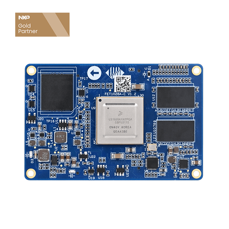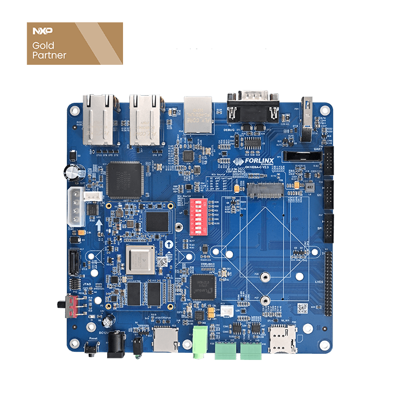
How to Output PWM Squareware by OK1028A-C development board
Some LS1028A development board users may have requirement of PWM squareware output, but there's no further related files for reference, so here today we'll introduce how to use OK1028A-C development board to output PWM squareware.Refer to OK1028A-C schematic and QorIQ LS1028A Reference Manual, we can get that 8 FlexTimer(FTM) are available on LS1028A, each FTM has 8 PWM channels.
Generally, we use PWM generated by FTM1, and here we'll use FTM7 for PWM testing.
12-14 of RCWSQ12 register is multiplexed with IIC4
IIC4 could be multiplexed to six different functions. Take OK1028A-C for example, we set it to RX and TX of CAN2, from OK1028A-C_V1.1 schematic we can see T6_CAN2_RX、U7_CAN2_TX. Then we can configure IIC3 to PWM by changing RCW.
OK1028A-C is enabled with PWM, so we do not need import any driver, and just need change pinmux and add PWM related node in device tree.
change IIC4_PMUX configuration in packages/firmware/rcw/ls1028ardb/RSQPP0x85bb/rcw1500gpu600.rcw, set pin to pwm output.
change IIC4_PMUX=2 to IIC4_PMUX=4
Then we need to change device tree code to add PWM related configuration.
target file path: packages/linux/linux/arch/arm64/boot/dts/freescale/fsl-ls1028a.dtsi
then add PWM7 device
Pwm7: pwm@2860000 {
                        compatible = "fsl,ls1028a-ftm-pwm";
                        reg =;
                        #pwm-cells =;
                        clock-names = "ftm_sys";
                        clocks = <&ftm_sysclk>;
                };
boot OK1028A-C
root@forlinx:~#cat /sys/kernel/debug/pwm to check current PWM device
PWM-1 is for backlight
compile updated device tree and firmware, then update them to OK1028A-C development board, boot system
root@forlinx:~#cat /sys/kernel/debug/pwm to check the current PWM device again
Even though the added PWM device is open, it is still different with PWM0, the new added PWM device has not been set with cycle and duty ratio.
So next we do not need add any driver code, can set PWM parameters by sys directly
Pwmchip8 is the target device to be added
Enable PWM
root@forlinx:~#echo 1 > /sys/class/pwm/pwmchip8/export
root@forlinx:~#echo 2 > /sys/class/pwm/pwmchip8/export
root@forlinx:~#cat /sys/kernel/debug/pwm
To cancel related PWM channel by below command
echo 1 > /sys/class/pwm/pwmchip8/unexport
echo 2 > /sys/class/pwm/pwmchip8/unexport
we can only enable one PWM channel every time, so here we set and run pwm1 firstly
root@forlinx:~#echo 1000000 > /sys/class/pwm/pwmchip8/pwm1/period
root@forlinx:~#echo 500000 > /sys/class/pwm/pwmchip8/pwm1/duty_cycle
root@forlinx:~#echo 1 > /sys/class/pwm/pwmchip8/pwm1/enable
Take a oscillograph to test 1KHz squarewave generated by T6_CAN2_RX
To enable pwm2, we need to turn off pwm1 firstly.
root@forlinx:~#echo 0 > /sys/class/pwm/pwmchip8/pwm1/enable
root@forlinx:~#echo 1000000 > /sys/class/pwm/pwmchip8/pwm2/period
root@forlinx:~#echo 500000 > /sys/class/pwm/pwmchip8/pwm2/duty_cycle
root@forlinx:~#echo 1 > /sys/class/pwm/pwmchip8/pwm2/enable
root@forlinx:~#cat/sys/class/pwm/pwmchip8/pwm2/{enable,period,duty_cycle}
Take a oscillograph to test 1KHz squarewave generated by U7_CAN2_TX
When working with OK1028A-C, you will find that many pins are multiplexed, and some functional pins are not available, but drivers are integrated. In this case, we just need to change related pinmux in RCW and device tree to enable related function.


