Common Problems and Troubleshooting Strategies During the Development of Forlinx Embedded Allwinner Series SoMs
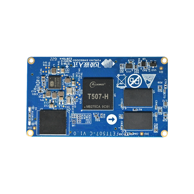
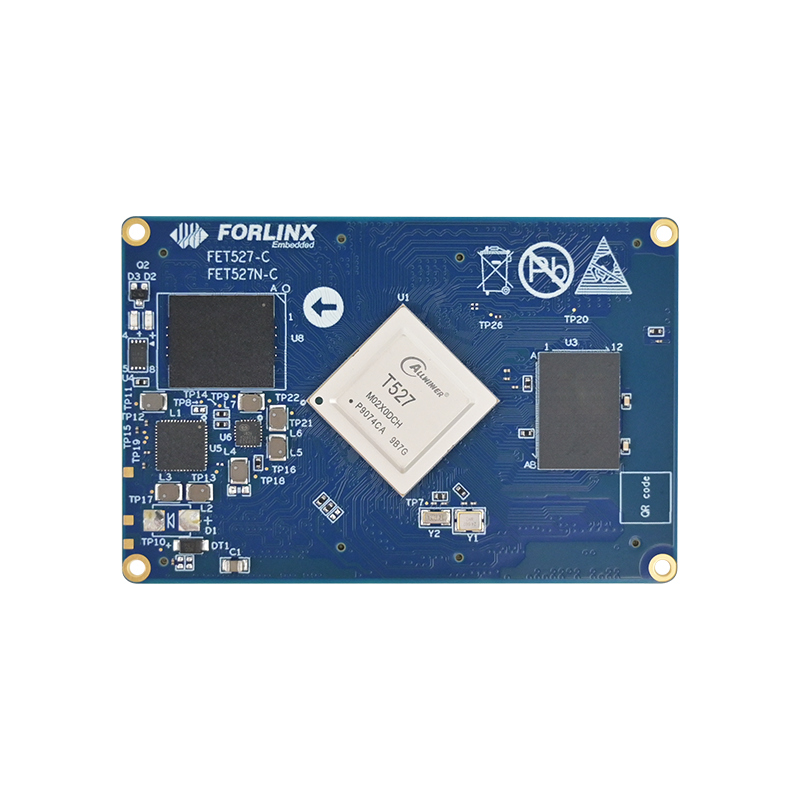
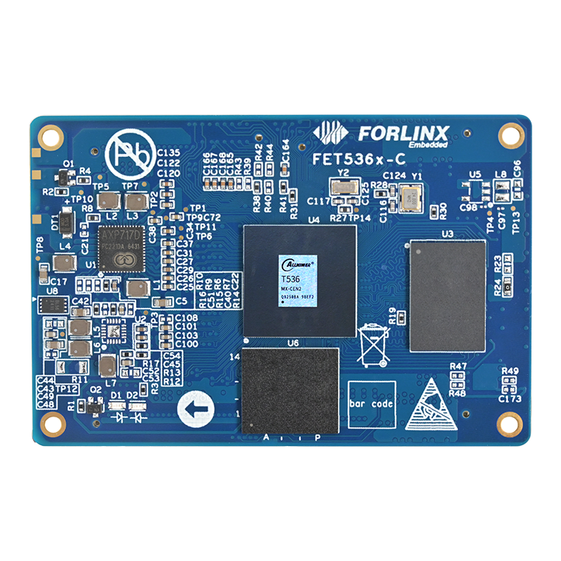
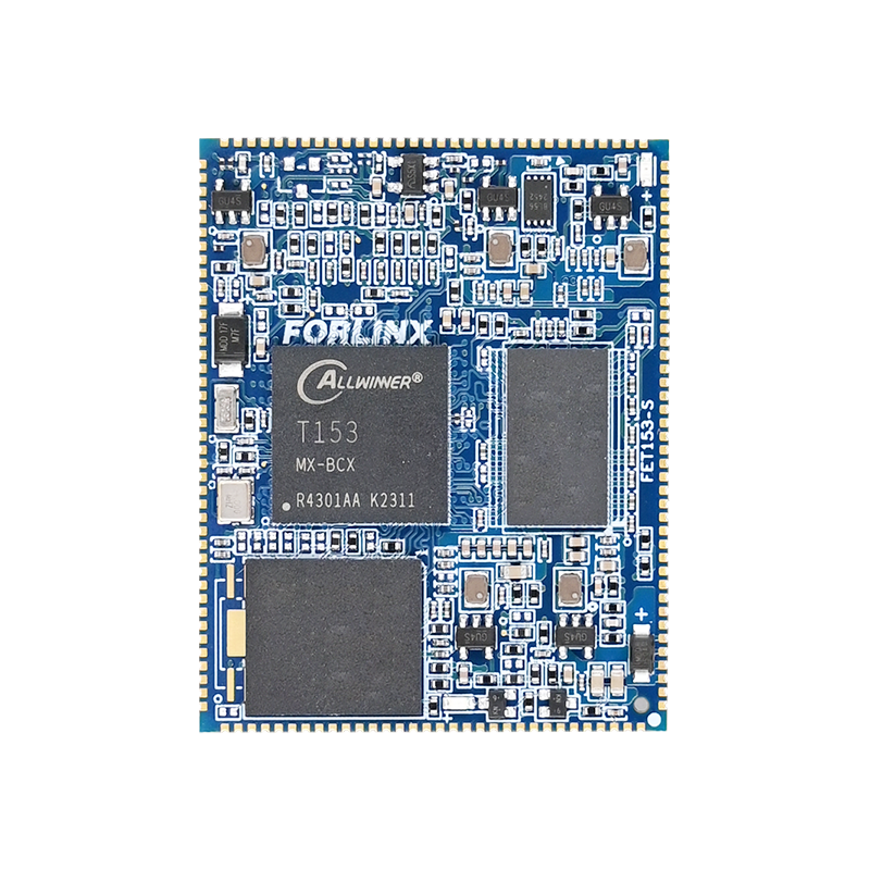
Forlinx Embedded has been collaborating with Allwinner Technology since 2019. Currently, Forlinx Embedded has launched 7 SoMs based on Allwinner processors, namely FETT507-C, FETA40i-C, FETT3-C, FET113i-S, FET527N-C, FET536-C, and FET153-S. These embedded main control products feature stable and reliable industrial-grade quality and high cost-effectiveness, winning wide recognition in the market. Thanks to years of close and in-depth cooperation, Forlinx Embedded recently became one of the first batch of ''Allwinner Technology Ecosystem Certified Partners''.
Forlinx Embedded has summarized common issues and troubleshooting methods encountered during the development of Allwinner series products through long-term technical support.
1. General Troubleshooting Ideas
For troubleshooting the Allwinner series master control, follow these general steps for any abnormal functions:
- (1) When referring to the functions of the carrier board designed by Forlinx Embedded: Ensure the consistency of the chips used and their principles. If the functional chips are different, it is necessary to transplant the chip drivers;
- (2) If the principle chips are consistent but the functional verification fails, check the power supply, reset, and clock status of the functional chips in sequence;
- (3) Conduct cross-testing to determine whether the problem lies in the SoM or the carrier board;
- (4) Check if the pin levels match and whether there is data signal output;
- (5) Investigate welding issues, and check if there are any cold solder joints, solder bridges, missed solder joints, or mis-soldered joints in the resistors and capacitors;
- (6) Measure whether the idle state of the signal is normal;
- (7) Confirm that the pin multiplexing is correct.
2. Common Problems and Solutions for Specific Modules
(1) Non-startup Issue
- In addition to power supply and reset, check whether the FEL signal is normal. Please remove the parallel capacitor to see if it affects the boot;
- Use an oscilloscope to measure the power supply waveform of the SoM to see if there are dips causing abnormal boot-up.
(2) I2C Bus Issue
- Since I2C is an OD output, first confirm whether there is a pull-up resistor;
- Confirm whether there are conflicts in the addresses of devices mounted on the same group of I2C buses;
- Measure the signal waveform to see if the idle state is at a high level and if the waveform is normal during data transmission;
- If the waveform rises slowly, please reduce the resistance value of the pull-up resistor. If the low-level is too high, please increase the resistance value of the pull-up resistor;
- Use the I2C tool to check whether there are devices mounted on the bus:
i2cdetect -l // Detect how many groups of I2C are on the system
i2cdetect -r -y 2 // Detect the devices mounted on the second group of I2C buses
(3) SPI Communication Issue
- Do not cross-connect the MISO and MOSI of the SPI interface;
- Confirm whether the chip-select signal is connected;
- Confirm whether the modes of the two communication devices are consistent;
- Measure whether the clock and data output are normal.
(4) USB Interface Issue
The positive and negative signals of USB cannot be cross-connected. Therefore, confirm whether the USB signal connection is correct.
(5) SDIO Interface Issue
- The SDIO signal cannot be converted through a level-conversion chip;
- If the speed does not meet the requirements, in addition to the pin level, confirm whether the SDIO bus has been subjected to equal-length processing;
- For the SDIO bus, first check whether the clock output is normal.
(6) LVDS Display Issue
- Check whether the output mode of the LVDS display screen is consistent with the screen (VESA and JEIDA);
- Confirm whether the 100Ω resistors of each differential signal of the LVDS screen are soldered;
- Measure whether the clock and data output are normal.
(7) Ethernet Network Problem
- Confirm whether the communication interface between the PHY chip and the MAC end is consistent and whether equal-length processing has been done;
- Check whether the MDIO bus is pulled up and whether the waveform is normal;
- Confirm whether the precision resistors meet the requirements;
- Check whether the reset time meets the chip requirements;
- Measure whether the crystal oscillator is oscillating;
- If the speed does not meet the requirements, check whether the power supplies of all paths and the reference ground are intact;
- Check whether the center taps of the network transformer are correct;
- Check whether there are conflicts in the addresses of different PHY chips on the same bus and whether they are consistent with the software;
- Check whether the MDI data lines have been subjected to equal-length processing and whether the impedance meets the requirements;
- Check whether the distance between the clock line and other lines meets three times the line width;
- Use an oscilloscope to measure whether there are sawtooth waves in the DCDC output by the chip.
(8) UART Problem
- The serial port transceiver signals need to be cross-connected;
- Confirm whether the serial port tool configuration is correct, such as the baud rate;
- Measure whether the data output is normal.
(9) RS485 Problem
- When there are multiple devices on the RS485 bus, confirm whether there are 120Ω matching resistors at both ends of the devices;
- If the RS485 devices cannot communicate, try to connect the reference grounds of the RS485 devices to reduce common-mode interference;
- Since RS485 is a half-duplex transmission, some RS485 chips require transceiver control signals. Confirm whether the chip driver has been added.
(10) Audio Problem
- If the original audio HPOUTL and HPOUTR are output in a direct-coupling manner, connect a capacitor to the ground for the HPCOMFB and HPCOM pins;
- If the system cannot detect the audio chip, check whether the I2C bus communication is normal;
- If the chip can be normally mounted but there is no sound output, first check whether the I2S data waveform is output normally, and then check whether the audio output is normal.
(11) CAN Bus Problem
- When there are multiple devices on the CAN bus, confirm whether there are 120Ω matching resistors at both ends of the devices;
- If the CAN devices cannot communicate, try to connect the reference grounds of the CAN devices to reduce common-mode interference.
3. Conclusion
With a systematic troubleshooting idea and modular solutions, you can efficiently deal with common development problems such as interface communication, signal integrity, and configuration logic. It is hoped that the practical experiences summarized in this article can provide clear solutions for you and help projects be implemented quickly.