With AMP Dual System Support, RK3568 SoM Boosts Real-Time Performance
What is AMP?
AMP (Asymmetric Multi-Processing) can be simply described as: Each core of a multi-core processor is isolated from the others, enabling them to run different operating systems or bare-metal (unmodified or native) programs relatively independently. This operational mode is particularly suitable for applications requiring high real-time performance.
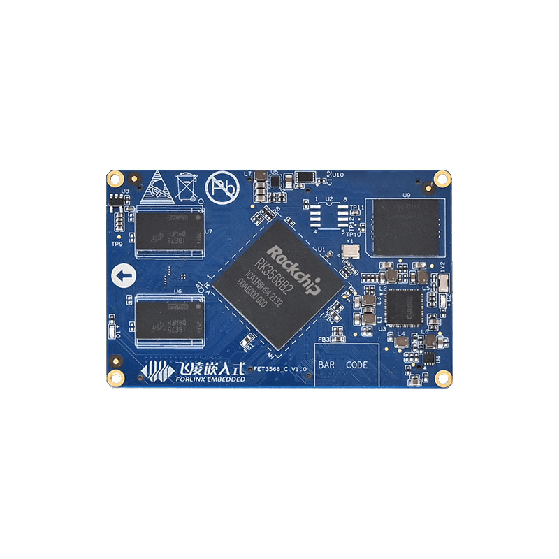
FET3568-C SoM AMP
The RK3568 processor on Forlinx's FET3568-C SoM features a quad-core Cortex-A55 architecture, classified as a homogeneous multi-core design.
The main difference between the RK3568's AMP SDK and Linux SDK lies in the different multiprocessor modes they use. The Linux SDK adopts the SMP mode, where a single Linux operating system manages all cores; while the AMP SDK uses the AMP mode, which divides the cores into two parts, with one part running the Linux operating system and the other part running bare-metal programs.
The bare-metal program operating mode, due to its direct hardware access characteristics, can efficiently handle high real-time tasks, meeting the stringent requirements for real-time performance in areas such as smart grid, power grid protection, power system security control, and industrial automation.
Advantages
(1) Lower cost:
The traditional approach to address the insufficient real-time performance of Linux system control is to use an external microcontroller to specifically execute high real-time programs.
The AMP system on the FET3568-C SoM simplifies the hardware architecture and reduces the hardware cost by separating a core as a real-time core to perform high real-time tasks.
(2) High real-time performance:
Because of the low real-time nature of the Linux system, it cannot be used to perform tasks that require high real-time performance. The real-time performance of bare-metal program or real-time operating system is much better than that of Linux system, while the high frequency of FET3568-C SoM makes A55 core have powerful real-time performance when running real-time system.
Inter-core Communication
Like other processors with multi-core heterogeneous architectures, AMP uses shared memory to transfer data between the A-core (Linux) and the real-time cores (bare-metal or real-time operating system).
Through physical memory DDR allocation, the hardware layer is divided into two parts: the TXVring Buffer (Transmit Virtual Ring Buffer) and the RXVring Buffer (Receive Virtual Ring Buffer); where the real-time core sends data from the TXVring area and reads the received data from the RXVring area, and vice versa for the A-core.
Example of AMP Usage
Currently, the Forlinx Embedded FET568-C SoM has provided usage examples for GPIO, UART, and SPI interfaces, utilizing RPMSG for inter-core communication. Other interfaces are still being adapted and will be opened later. Bare metal programs can be debugged using JLINK emulation in the tools provided.
The following is a brief example of the use of the UART interface in a bare-metal application:
(1) Hardware connection
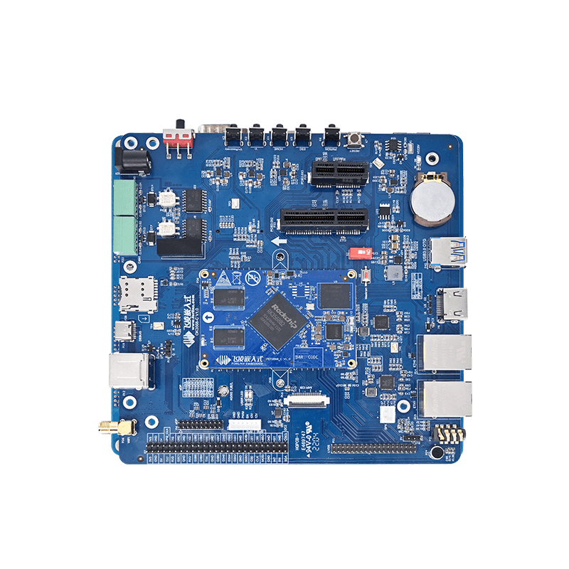
This example uses UART5 and uses a jumper cap to short TX5 to RX5 on the OK3568-C development board.
(2) Device tree configuration:
To prevent Linux from taking up the resources of UART5 and causing the real-time core to be unable to use UART5, it is necessary to first add resource protection for UART5, including clock and pinctrl, to the rockchip_amp node in the device tree.
(3) Configuration of bare metal program
Introduction to UART interface:
//Pin configuration: select the transceiver pin of UART5. /* uart5 tx */
HAL_PINCTRL_SetIOMUX(GPIO_BANK3, GPIO_PIN_C2, PIN_CONFIG_MUX_FUNC4);
/* uart5 rx */HAL_PINCTRL_SetIOMUX(GPIO_BANK3, GPIO_PIN_C3, PIN_CONFIG_MUX_FUNC4);
/* uart5 m1 */ HAL_PINCTRL_IOFuncSelForUART5(IOFUNC_SEL_M1);
//Communication configuration: Baud rate is 115 200, no check, data bit is 8, no flow control, stop bit is 1.
/* uart5 config */struct HAL_UART_CONFIG demo_uart_config = {
.baudRate = UART_BR_115200, // Baud rate
.dataBit = UART_DATA_8B, // Bit
.stopBit = UART_ONE_STOPBIT, // Bit
.parity = UART_PARITY_DISABLE, //Check
}; HAL_UART_Init(&g_uart5Dev, &demo_uart_config);
Interrupt Enable: Configure and enable the receive timeout interrupt.
HAL_IRQ_HANDLER_SetIRQHandler(UART5_IRQn, uart5_isr, NULL);
HAL_GIC_Enable(UART5_IRQn);
HAL_UART_EnableIrq(g_uart5Dev.pReg, UART_IER_RDI);// Execute the process
// After the initialization is completed, a string of data is sent first. If data is received, an interrupt is triggered and the received data is sent out of the debug serial port.
// Interrupt callback function int iir = 0;iir = HAL_UART_GetIrqID(g_uart5Dev.pReg);
if (iir & UART_IIR_RX_TIMEOUT) {
do {
ret = HAL_UART_SerialIn(g_uart5Dev.pReg, &c, 1);
if (ret)
printf("%02x ", c);
} while (ret);
printf(“\n”);
}
Example Uses:
According to the manual provided in the OK3568-C development board product documentation, call the use routine we have written in the main function of the bare metal program.
Experimental Phenomena:
After compiling and flashing the program according to the manual, open the serial port debugging assistant and the corresponding serial port, you can see the data sent out by the program after the OK3568-C development board is powered on.
In the serial port debugging assistant, input any data and send it, trigger the receive interrupt, and the input data can be seen from the real-time kernel debugging serial port (uart4).