Fixing Ethernet Packet Loss Issues on Self-made RK3568 Carrier Board through RGMII Delayline Adjustment
When using the Forlinx RK3568 system on module(SoM) with a self-made carrier board, due to the differences between the PCB traces and the reference design, it often leads to abnormal timing of the RGMII interface, resulting in situations where the network port does not work or there is frequent packet loss. This article provides a clear and efficient debugging solution. Such problems can be resolved through three simple steps.
1. Test Conditions
① Hardware: Forlinx RK3568 SoM;
② System: Linux 4.19.206;
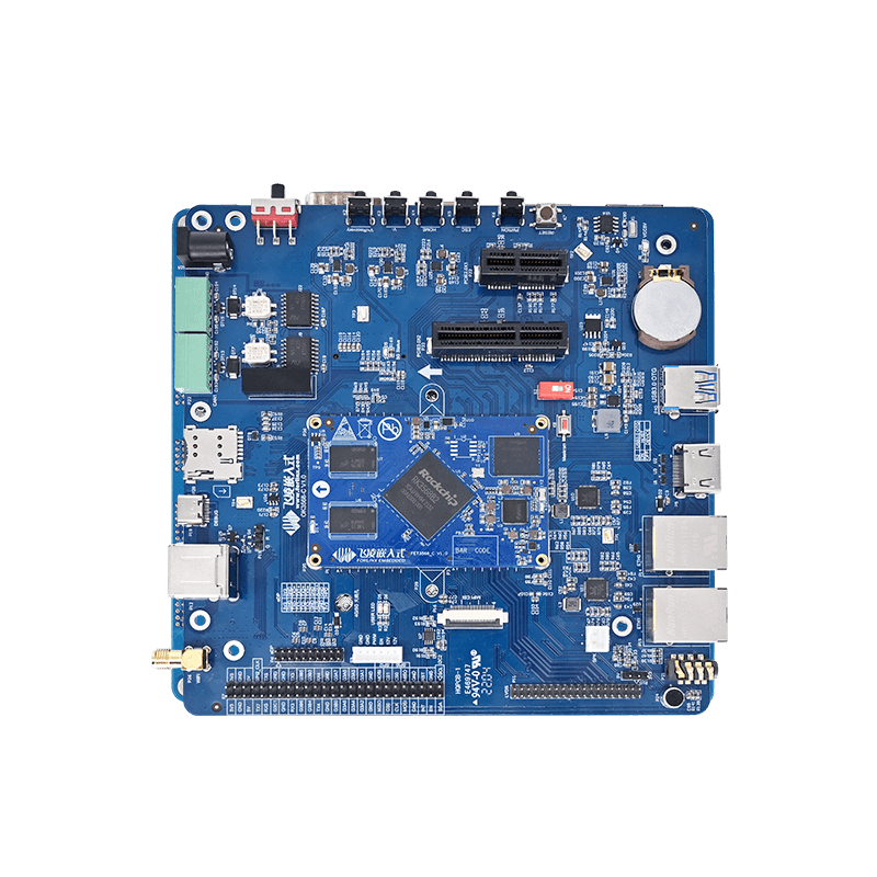
③ Carrier board: A user - self - made carrier board. The carrier board design basically follows the reference schematic diagram of the RK3568 SoM provided by Forlinx, but there are differences in the PCB traces;
④ Problem: The network port cannot be connected or there is severe network packet loss.
2. Debugging Steps
① Confirm the system nodes (taking RK3568 as an example)
- Enter the directory: /sys/devices/platform/fe300000.ethernet
- Confirm the existence of the following key nodes:
phy_lb_scan
rgmii_delayline
phy_lb
② Scan the Delayline window (obtain the intermediate value)
Important reminder: If you are using the RTL8211E PHY chip, make sure to unplug the network cable before testing!
- Scan at a 1000M (gigabit) rate:
echo 1000 > phy_lb_scan
③ Test the Delayline values obtained from the scan
- Write the tx_delay and rx_delay values obtained from the scan in step 2 into the rgmii_delayline node for temporary configuration:
echo> rgmii_delayline #for example: echo 0x2e 0x0f > rgmii_delayline
cat rgmii_delayline # The value just written should be displayed.
echo 1000 > phy_lb # Use gigabit speed test
It is necessary to ensure that the phy_lb loopback test passes. This is the basis for subsequent operations. If the test fails, you may need to rescan or check the hardware.
④ Solidify the configuration into the Device Tree (DTS) and flash the firmware
- After the phy_lb test passes, write the valid tx_delay and rx_delay values obtained from the test into the GMAC node in the Device Tree Source file (DTS);
- Locate the part that defines gmac in the DTS file of RK3568 (usually in rk3568.dtsi or the board - level DTS file);
- Modify the attribute values of tx_delay and rx_delay to the values that passed the test:
&gmac {
assigned-clocks = <&cru SCLK_RMII_SRC>;
assigned-clock-parents = <&clkin_gmac>;
clock_in_out = "input";
phy-supply = <&vcc_lan>;
phy-mode = "rgmii";
pinctrl-names = "default";
pinctrl-0 = <&rgmii_pins>;
snps,reset-gpio = <&gpio3 RK_PB7 GPIO_ACTIVE_LOW>;
snps,reset-active-low;
snps,reset-delays-us =;
tx_delay =;  //Replace with a valid tx _ delay value from the scan test in hexadecimal
rx_delay =; //Replace with a valid rx _ delay value (hex) from the scan test
status = "okay";
};
⑤ Final verification
- After the device is started, conduct a network connection test:
- Generally, after completing the above steps and passing the verification, the problems of the network port not working or packet loss should be solved;
Use the ping command to test network connectivity and stability.
Use tools such as iperf3 to conduct network bandwidth and performance tests to check if there is still packet loss.
3. Important reminders
① Operational risks:
Modifying RGMII delayline parameters is a low-level hardware optimization. Incorrect parameters may cause the network port to fail completely. It is strongly recommended to back up the original firmware and DTS files before operation.
② Necessity of testing:
Step 3 (phy_lb loopback test) must pass before the parameters can be written into the DTS. Skipping this test and directly solidifying the parameters is extremely risky.
③ Hardware differences:
This method mainly solves the timing problems caused by differences in PCB traces. If the self - made carrier board is very different from the reference design or there are other hardware failures, this method may not be effective.
④ Parameter values:
The 0x2e and 0x0f in the example are only for format illustration. You must use the actual valid values obtained through phy_lb_scan scanning and verified by the phy_lb test.
4. Summary
When encountering RGMII timing deviation problems caused by differences in PCB traces when using a self-made RK3568 carrier board, use the three-step “scan-verify-solidify” first-aid method: echo to scan the optimal tx/rx_delay → phy_lb loopback verification → one-click writing to the DTS, and the crashed network port can be revived on the spot.
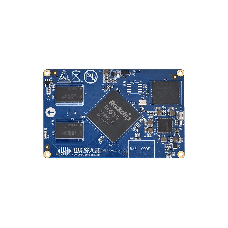
The FET3568-C SoM of Forlinx Embedded is developed and designed using the Rockchip RK3568 processor. This processor is a high-performance, low-power, and feature-rich application processor created by Rockchip for the AIoT and industrial markets. It features a quad-core 64-bit Cortex-A55 architecture with a main frequency of up to 2.0GHz, and has a built-in NPU with a computing power of 1TOPS. It has also undergone rigorous environmental temperature tests, stress tests, and long-term stability operation tests to ensure its stable and reliable operation.