Allwinner T507 Core Board FAQ Analysis
In this paper, the hardware platform adopts Allwinner T507 quad-core vehicle standard-level processor design core board, this paper is organized in the use of Forlinx embedded T507 product process species, often encountered several problems, other board settings, please refer to the use.
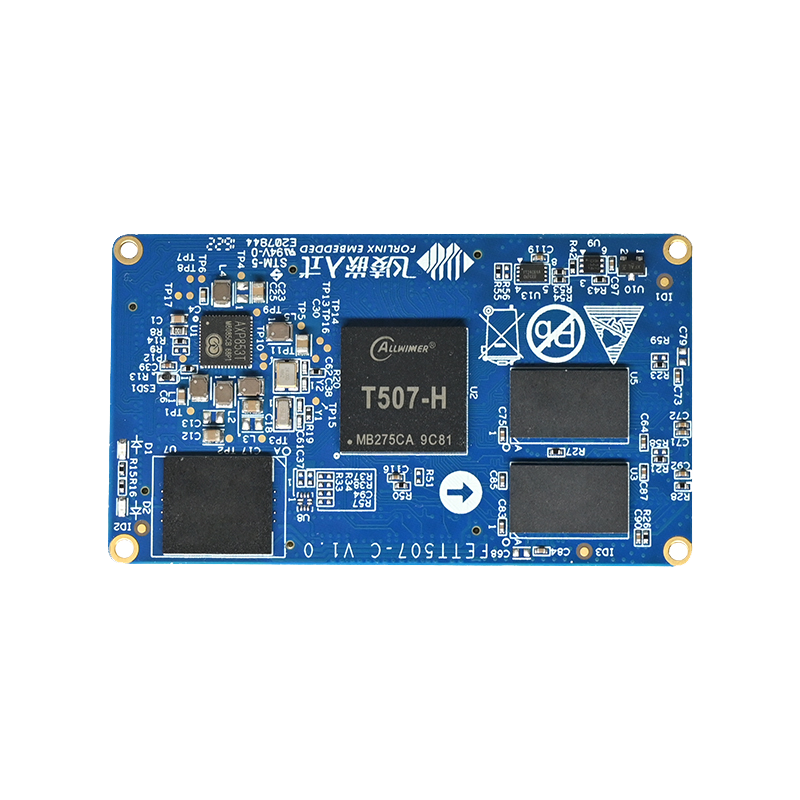
Forlinx embedded Allwinner T507 series hardware introduction
FETT507-C core board integrated Allwinner T507 quad-core vehicle standard-class processor design and development, Cortex-A53 architecture, main frequency 1.5GHz, integrated G31 GPU, memory 2GB DDR3L, storage 8GB eMMC. The whole board industrial-grade operation temperature is wide, supports most of the current popular video and picture format decoding, with stable and reliable industrial-grade product performance, low power consumption and rich user interface and other advantages, equipped with Linux, Android, Ubuntu operating system, suitable for automotive electronics, power, medical, industrial control, Internet of Things, intelligent terminals and other fields.
Question 1: How to modify the power-on LOGO later using the T507 core board
If you need to replace the power-on LOGO during the T507 process, you only need to replace it OKT507-linux-sdk/device/config/chips/t507/boot-resource/boot-resource/bootlogo.bmp
If the logo size is smaller than the screen size, the black background will be filled in the remaining space, and to avoid image amplification distortion or the surrounding black fill, you can select a LOGO picture of the same size as the screen. Or modify the device tree for background color fill.
Replace the power-on LOGO recompil kernel burn t507_linux_okt507_uart0.img.
Note: LOGO cannot be larger than the fbX_width and fbX_height property values in the device tree.
Question 2: How the T507 core board is recalibrated using a resistance screen
When you use the resistance screen for the T507, you need to use tslib calibration by default, and if you need to recalibrate:
/usr/bin/ts_calibrate
The calibration file is saved at /etc/pointercal
Question 3: GPIO configuration for the T507 core board Uboot phase
The T507 core board can be configured in the device tree if you need to set the GPSO output high and low level during the Uboot phase, referring to the power pin of The LVDS of Forlinx.
A total of 32 pins are currently supported for gpio0-gpio31 configuration. For the meaning of pinctrl, please refer to the < T507 core board pages>of the database information and the original data catalog.
Question 4: Settings for the default environment variable for the T507 core board
The default environment variable profile for T507 is saved at: device/config/chips/t507/configs/default/env.cfg
If you need to modify or add the default environment variables, you can edit the file directly.
Question 5: T507 core board alienation settings
If you need to adjust the display mode of the T507 to asynchronous display, you can adjust it according to the following steps.
- 1, first of all in the uboot menu configuration display mode is heterogeneous
- 2, configure the sub-screen information, here to 1080P hdmi as an example.
- 3, start the system
- 4, close the Forlinx desktop program/etc/init.d/S60Matrix_Browser stop
Home program script: f.sh
#/bin/sh
export QT_QPA_EGLFS_FB=/dev/fb0
export QT_QPA_EGLFS_HEIGH=480
export QT_QPA_EGLFS_WIDTH=800
export FRAMEBUFFER=/dev/fb0
/usr/bin/fltest_qt_4g&
Sub-screen program script: s.sh
#/bin/sh
export QT_QPA_EGLFS_FB=/dev/fb1
export QT_QPA_EGLFS_HEIGH=1080
export QT_QPA_EGLFS_WIDTH=1920
export FRAMEBUFFER=/dev/fb1
/usr/bin/fltest_qt_keypad
F.sh and s.sh can be performed separately to make the difference.