How to Choose An Embedded Board?
How to Choose An Embedded Board?
The development of embedded systems starts with hardware, the IoT segment with increasingly complex application requirements, and the challenge of rapid iteration and cost-effectiveness, choosing an off-the-shelf suite for wireless sensor prototyping and debugging is a solution that combines development efficiency and cost-effectiveness, while a comprehensive software environment and optimized hardware platform accelerate your development progress.
Advanced Industrial, Medical, Transportation, and Agricultural Internet of Things (IoT) applications require more complex embedded system designs. In this case, despite tighter schedules and shrinking budgets, developers have no choice but to make their own boards to meet performance, connectivity, and peripheral requirements. Even if there may be off-the-shelf boards, performance, power consumption, size, form factors, and functionality limit their suitability.
However, in an era of Ubiquitous Internet of Things and Industrial Internet of Things (IoT), even the most efficient custom development teams can be delayed by regional certification requirements for wireless subsystems, slowing delivery and losing market opportunities.
This article will discuss the wireless embedded development board "build and buy" problem. Then introduce a new product from Forlinx, and this article shows how to use the suite to help developers quickly and easily deliver more powerful embedded system solutions.
Homemade or purchased: How to choose an embedded development board?
With end-user product expectations and market competition pressures, embedded system developers need to provide more functionality within a shrinking time-to-market window. Users prefer systems that are easier to connect, use, and maintain. As a result, developers face growing challenges in many ways.
For wireless connectivity, short- and long-range wireless solutions introduce design certification requirements, implementing the right display capabilities increases design complexity and cost, and ensuring the continued reliability and long-term availability of these systems challenges developers to find solutions that can withstand harsh conditions and remain available for long life cycles common in industrial or medical applications.
For some applications, the right solution relies heavily on a customized design approach to optimize each subsystem to meet the requirements. However, an increasing number of off-the-shelf design solutions provide a platform that can be easily scaled to support the unique requirements of a wide range of applications.
However, development teams sometimes decide to build custom solutions purely from a development cost perspective rather than buy pre-built systems, and they calculate that building custom designs from scratch is less expensive than buying off-the-shelf designs.
In fact, the development team will find that other considerations, including wireless authentication, availability, maintainability, and other lifecycle issues, increase overall costs. In a fast-growing market, delays in implementing custom designs further erode market share and revenue timeliness, ultimately limiting the profitability of new products.
To address these issues, Forlinx has introduced the imx8m plus development kit, an effective alternative to custom development, providing a platform that meets the performance and cost requirements of a wide range of applications.
iMX8M Plus Embedded Board: Meets Different Functional Needs
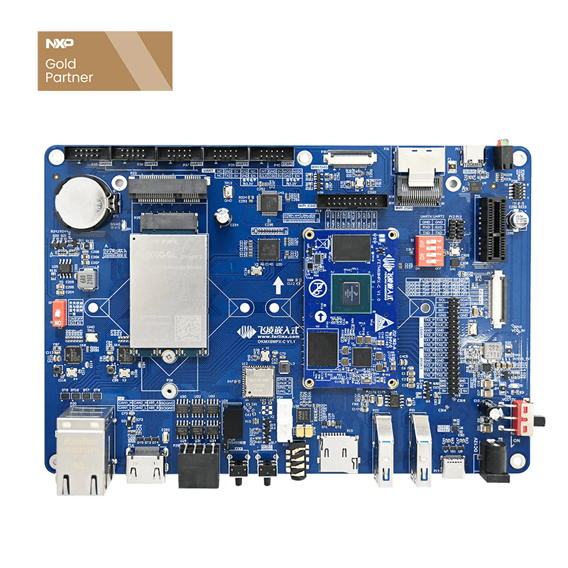
The imx8m plus development kit provides a comprehensive hardware platform that reduces development time and system time-to-market. With this suite, developers can easily implement scalable systems to support applications such as human-machine interface (HMI) design, audio/video processing, edge computing, machine learning, and more. In addition to the imx8m plus board, the kit includes dual-frequency antennas, console port cables, and power supplies, so developers can start creating interconnect applications right away.
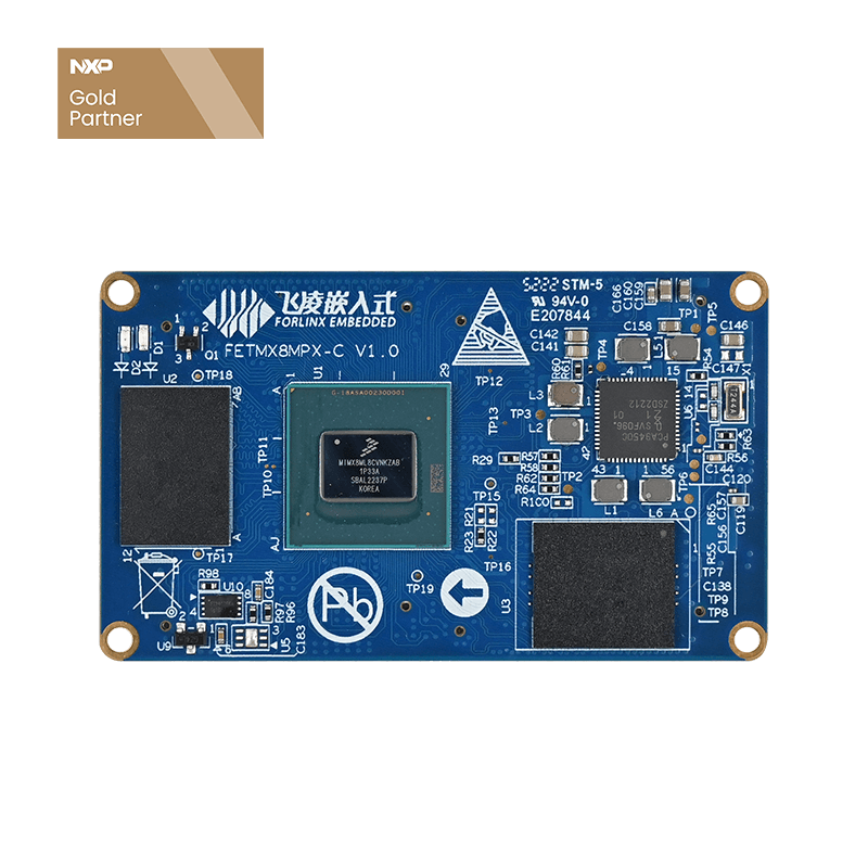
Forlinx's imx8m plus SoM with NXP's Based on the i.MX8 processor family, it integrates the capabilities required for typical embedded applications such as multimedia, security, wired connectivity, and pre-certified wireless connectivity. Combined with a broad software environment, these SoMs simplify the development of embedded systems, allowing product manufacturers to deliver more complex products faster and at lower risk than the custom hardware approach typically used.
For the imx8m plus development kit, SoM combines the capabilities of NXP's quad-core Arm Cortex-A53 and Arm Cortex-M7 core i.MX 8M plus processors, as well as up to 8 GB of flash memory, up to 1 GB of low-power double data rate (LPDDR) dynamic random access memory (DRAM) and a range of additional subsystems.
SoM's built-in connectivity options support Gigabit Ethernet (GbE) and pre-certified 802.11a/b/g/n/ac Wi-Fi and Bluetooth 5.0.
In addition to a full range of standard peripheral interfaces, SoM supports a wide range of multimedia interfaces for audio, cameras, and displays. The integrated graphics processing unit and LCD interface controller make it easy for developers to add optional LCD panels, such as imx8m plus, and quickly start creating HMI designs for their embedded applications.
Summary
The increasingly complex application needs in segments such as industry, healthcare, transportation, and agriculture are driving the need for more complex embedded system designs for the Internet of Things. Regional certification requirements for related wireless subsystems also complicate the problem and slow down the design.
To address these issues, Forlinx has introduced a development kit that provides designers with a comprehensive software environment and an optimized hardware platform with pre-certified wireless modules. As mentioned above, the suite makes it easier and faster for developers to deliver powerful interconnect embedded system solutions. Details can be found online.
iMX8M Plus Embedded Board Video
OKMX8MP-C Embedded Board Demo | NXP iMX8M Plus processor based
iMX8M Plus Embedded Board Function Parameter
Note: The parameters in the table are hardware design or CPU theoretical values.
| iMX8M Plus Embedded Board Function Parameter | ||
|---|---|---|
| Peripheral source | QTY | Parameter |
| USB3.0 Type-C | 1 | USB 3.0 of USB Type-C supports DFP, UFP and DRP |
| USB3.0 | 2 | USB Type A socket lead out, only used as Host |
| MIPI_CSI | 2 | CSI1: daA3840-30mc-IMX8MP-EVK, resolution 3840X2160CSI2: OV5645, the camera supports a maximum resolution of 2592X1944 |
| MIPI_DSI | 1 | The backplane leads to the 4 lane MIPI_DSI interface through the FPC socket, which is adapted to the Forlinx 7-inch MIPI screen by default, with a resolution of 1024 x 600@30fps. |
| LVDS | 1 | LVDS 1 dual asynchronous channels (8 data, 2clocks) support 1920x1200p60, all signals are led out |
| HDMI | 1 | Support HDMI 2.0a display resolution up to 4K@30fps Support HDMI2.1 eARC |
| Ethernet | 2 | Support 10/100/1000Mbps self-adaption, lead through RJ45. One of them supports TSN |
| PCIE | 1 | The backplane adopts standard PCIEx1 card interface and supports PCI Express Gen3 |
| TF Card | 1 | The development board supports one TF Card, and can support UHS-I TF cards, with a rate of up to 104MB/s. |
| 4G | 1 | Use it with 5G modules, support 4G modules using miniPCIE sockets, and use Quectel EC20 by default |
| 5G | 1 | Use it with 4G modules, support 5G modules using M.2 Key B socket, and use Quectel RM500Q by default |
| WiFi | 1 |
The default onboard AW-CM358M IEEE 802.11 a/b/g/n/ac dual-band WIFI, up to 433.3Mbps transceiver rate; Bluetooth 5, up to 3Mbps rate |
| Bluetooth | 1 | |
| Audio | 1 | The development board is adapted to the WM8960 chip, the headphone output and MIC input are integrated into a 3.5mm headphone jack, and it supports 2 channels of 1W8Ω speaker output, which are led out through the XH2.54 white terminal. |
| I2C | 3 | Used to mount audio, RTC, camera and other equipment on the backplane. |
| PWM | 2 | Used to adjust the backlight brightness of the display |
| RTC | 1 | With independent RTC chip on board, the time can be recorded by button battery after the bottom board is powered off. |
| UART | 4 | The backplane board carries USB to 4 serial ports, which are led out through socket pins for users to plug in equipment. |
| ECSPI | 1 | The development board leads to ECSPI2 through a 2 x 5 2.0mm pitch socket for users to plug in equipment. |
| CAN | 2 | Electrical isolation, support CAN-FD (requires CPU version support), and conform to CAN2.0B protocol |
| RS485 | 1 | Electrical isolation, automatic control of the sending and receiving direction. |
| KEY | 4 | Switch machine, reset button, and 2 user-defined buttons. |
| LED | 2 | User-defined LED lights, red and green. |
| DEBUG UART | 2 | Cortex-A53 and M7 debug serial port, the default baud rate is 115200 |
| JTAG | 1 | The development board leads to the JTAG signal through a 2 x 5 2.0mm pitch socket. |
Note: The parameters in the table are hardware design or CPU theoretical values.
How To Buy iMX8M Plus Embedded Board?
1. Order Online
We have an online store on Alibaba, please contact us to start ordering
2. Order offline
pls send your inquiry to our mailbox [email protected];
3. Payment Terms
Samples(100% T/T in advance), Bulk Order(please contact with our sales)