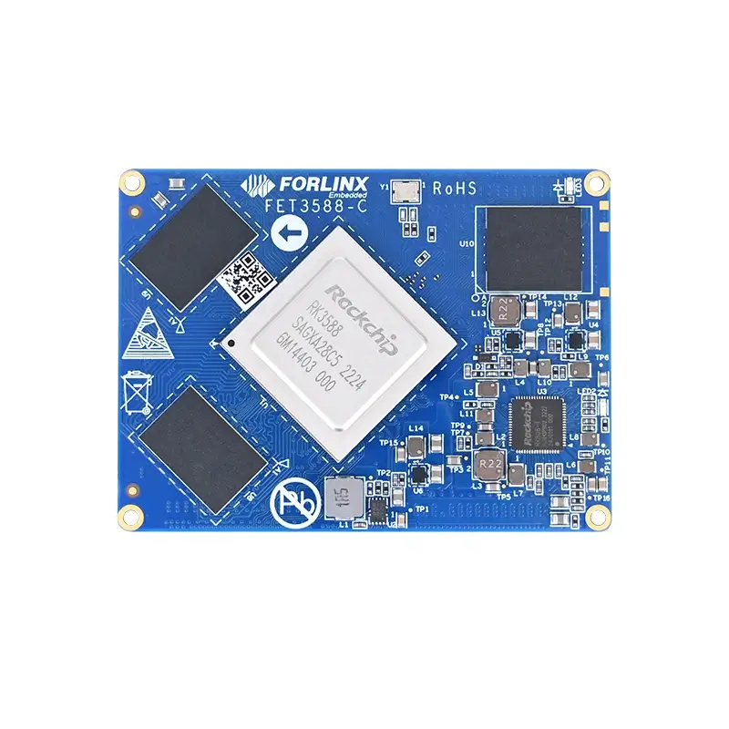

OK3588-C Linux 5.10.209 PCIe Endpoint Function Configuration and Test
In high-performance embedded systems, PCIe can not only be used to connect traditional peripherals such as NVMe SSDs and network cards, but also be used for high-speed communication between SoCs. When one RK3588 is used as a PCIe Root Complex and the other is configured as a PCIe Endpoint, the PCIe link can be used to establish a high-speed data channel between the two processors.
Based on OK3588-C platform, the software and hardware configuration process of RK3588 PCIe Endpoint function is arranged, and the identification, link negotiation and DMA test methods of RC and EP are described with the actual test screenshots.
1. Test Scenario and Critical Constraints
Test Topology
In this test, two RK3588 cards are directly connected: one is used as the PCIe RC end, and the other is used as the PCIe EP end. The test data version is "OK3588-C & OK3588-C21 _ Linux 5.10.209 _ User Data _ R2".
| Main Chip | Solution | SMBus Extension | Independent Clock Scheme |
| RK3568 | Supports Flash Boot and Common Boot; does not support PCIe Boot. | N | Supports SRNS; does not support SRIS. |
| RK3588 | Supports Flash Boot and Common Boot; does not support PCIe Boot. | N | N |
| RK1820 | Supports Flash Boot and Common Boot; does not support PCIe Boot. | Y | N |
Reference Clock Limitation
When the RK3588 operates as a PCIe Endpoint, it does not support the SRNS (Separate Refclk Independent Spread) non-common-reference-clock scheme. Therefore, the Endpoint must use a common PCIe reference clock provided by the Root Complex (RC). In this test, the Endpoint uses the 100 MHz reference clock provided by the RC.
|
Note: • The original PCIe reference clock at the EP side must be disconnected to prevent interference caused by simultaneous driving from both the RC clock and the EP’s local clock; • The corresponding defconfig must be enabled in the EP-side U-Boot; the specific image and configuration should be consistent with the software version in use. |
2. EP-side Software Configuration
In the RK3588 Linux 5.10.209 source code, basic support for the PCIe Endpoint function is already in place. The software-side configuration mainly involves setting up the device tree, Kernel defconfig, BAR space, and HugePage.
Device Tree: Switching to Endpoint Mode
Configure the PCIe controller node to operate in the standard Rockchip Endpoint mode and bind the reserved-memory region for BAR mapping. Key configuration example is as follows:
&pcie3x4 {
compatible = "rockchip,rk3588-pcie-std-ep";
memory-region = <&bar0_region>, <&bar2_region>;
memory-region-names = "bar0", "bar2";
reset-gpios = <&gpio4 RK_PB6 GPIO_ACTIVE_HIGH>;
rockchip,ep-power-independent;
vpcie3v3-supply = <&vcc3v3_pcie30>;
status = "okay";
};
The compatible attribute determines that the controller works in PCIe Endpoint mode, and the memory-region is used to specify the reserved memory used by the BAR mapping at the EP side.
Reserve BAR Mapping Space
reserved-memory {
#address-cells = <2>;
#size-cells = <2>;
ranges;
bar0_region: bar0-region@3c000000 {
reg = <0x0 0x3c000000 0x0 0x00400000>;
};
bar2_region: bar2-region@40000000 {
reg = <0x0 0x40000000 0x0 0x04000000>;
};
};
BAR0 reserves 4 MB of space.
BAR2 reserves 64 MB of space.
These spaces are used for address mapping and subsequent DMA data access between RC and EP. The actual product should be adjusted according to the data window, DMA buffer and memory planning of the application.
Kernel Defconfig Configuration
CONFIG_PCIE_DW_ROCKCHIP_EP=y
CONFIG_HUGETLBFS=y
CONFIG_PCIE_FUNC_RKEP=y
CONFIG_ARCH_ENABLE_HUGEPAGE_MIGRATION=y
CONFIG_HUGETLB_PAGE=y
Among them, CONFIG_PCIE_DW_ROCKCHIP_EP is used to enable Rockchip DesignWare PCIe Endpoint controller support; CONFIG_PCIE_FUNC_RKEP is used to enable the Rockchip PCIe EP function. The HugeTLB related options are used for subsequent large contiguous memory and DMA testing.
BAR Parameter Configuration
The test plan also requires adjusting the Resizable BAR related configurations in the Rockchip PCIe EP driver based on the layout of BAR0, BAR2, and BAR4. The corresponding source code is located at:
drivers/pci/controller/dwc/pcie-dw-ep-rockchip.c
In the original test plan, the configurations related to BAR0, BAR2, and BAR4 were updated to match the parameters of the test space. Special attention is required: When the BAR space size changes, the related configurations in the Linux kernel, device tree, and U-Boot must remain consistent.
HugePage Configuration
To facilitate PCIe large-block data transfer testing, this plan uses the HugePage method recommended by Rockchip to prepare contiguous memory. Add the following to the bootargs:
default_hugepagesz=32M hugepagesz=32M hugepages=16
This means the default HugePage size is 32 MB, with a total of 16 HugePages reserved. This configuration primarily serves the test Demo and DMA data buffering. For mass production projects, it should be re-planned according to the actual memory capacity and application requirements.
3. EP-side Hardware Clock Modification
The PCIe high-speed link has high requirements for reference clock stability and topology. Since the RK3588 EP does not support the non-common-reference-clock scheme, this test configures the EP to directly use the 100 MHz PCIe reference clock output from the RC, while simultaneously disconnecting the original reference clock path on the EP board.
Figure 1 Schematic Diagram Related to the PCIe Reference Clock (Original Test Data Screenshot)
Figure 2 Hardware Modification Location for the EP Board Reference Clock (Photo of Original Test Data)
|
Hardware Design Key Points: • The Root Complex (RC) and the Endpoint (EP) must share the same PCIe reference clock; • Avoid connecting both the RC reference clock and the EP’s local reference clock simultaneously; • For formal customized hardware, it is recommended to clearly define the REFCLK topology and the 0Ω resistor/optional paths during the schematic design phase to minimize post-production modifications such as wire jumping or board rework. |
4. RC-side Software Configuration
The RC side still operates in PCIe Host mode, but it needs to enable the Rockchip RKEP function and HugePage support to recognize the EP device and complete subsequent testing.
Enable the RKEP Function
CONFIG_PCIE_FUNC_RKEP=y
Enable the HugeTLBFS
CONFIG_HUGETLBFS=y
Configure HugePage
default_hugepagesz=32M hugepagesz=32M hugepages=16
At this point, the basic software configuration for both the RC and EP sides is complete, allowing entry into the hardware connection and functional testing phase.
5. Hardware Connection and Power-up
The PCIe Endpoint does not support hot-plug. During testing, the PCIe connection between the RC and EP should be established first, followed by powering on the system, to avoid plugging or unplugging the EP link while the device is already running.
Figure 3 Diagram of the Connection Relationship between RC and EP Boards (Original Test Data Screenshot)
Figure 4 Actual Connection Status of RC/EP (Original Test Data Photo)
|
Recommended Power-up Sequence: • Connect the PCIe interface between the RC and EP; • Verify that the 100 MHz reference clock path and hardware modifications are correct; • Then power on the system; • After startup, check the device nodes and link status on both the RC and EP sides respectively. |
6. RC-side Functional Verification
Checking RKEP Driver and Device Identification
dmesg | grep rkep
When both software and hardware configurations are correct, you should see logs indicating successful MSI interrupt requests, VID/DID information, and RKEP object details.
pcie-rkep 0000:01:00.0: success to request msi irq
pcie-rkep 0000:01:00.0: vid=1d87
pcie-rkep 0000:01:00.0: did=356a
pcie-rkep 0000:01:00.0: obj_info magic=524b4550, ver=100
Check device nodes
ls /dev/pcie-rkep-0000\:01\:00.0
View the link rate and number of channel
cat /sys/bus/pci/devices/0000\:01\:00.0/current_link_speed
cat /sys/bus/pci/devices/0000\:01\:00.0/current_link_width
In this test, the link negotiation result is 8.0 GT/s with a Link Width of 4, establishing a PCIe Gen3 ×4 link.
Figure 5: RC-side RKEP Identification, Device Node, and PCIe Gen3 ×4 Link Verification (Original Test Data Screenshot)
7. EP-side Status Verification
After the EP side boots normally, you can check the Endpoint device node:
ls /dev/pcie_ep
Figure 6: EP-side /dev/pcie_ep Device Node (Original Test Data Screenshot)
Once both the RC and EP sides are correctly identified, you can proceed to further PCIe read/write and DMA performance testing.
8. Compiling and Running the Speed Test Demo
Rockchip provides test demos for the PCIe Endpoint standard card. Since the original test data was compiled in a Linux environment, you need to first copy the resource package to the development environment, extract it, and then modify the cross-compilation toolchain path in build.sh.
Rockchip_PCIE_EP_Stardard_Card_20250916/build/linux/build.sh
Figure 7: build.sh Cross-Compilation Toolchain Path Configuration (Original Test Data Screenshot)
After modifying the toolchain path, execute:
./build.sh
Figure 8: PCIe Test Demo Compilation Process (Original Test Data Screenshot)
This test uses the pcie_speed_test speed measurement demo. The compilation output and program location can be referenced in the figure below.
Figure 9: pcie_speed_test Speed Test Program (Original Test Data Screenshot)
For more detailed parameters and usage instructions, refer to the README in the resource package:
Rockchip_PCIE_EP_Stardard_Card_20250218/examples/pcie_speed_test/README.md
Figure 10: pcie_speed_test README Usage Instructions (Original Test Data Screenshot)
9. Actual Testing of EP-DMA and RC-DMA
EP-DMA Mode
EP-DMA is the default testing method, and generally no modification to the DMA selection configuration in the driver or test program is required. Run the speed test program on the RC side and EP side separately to observe the link working status and data transfer results.
Figure 11: Speed Test Output on the RC Side in EP-DMA Mode (Original Test Data Screenshot)
Figure 12: Speed Test Output on the EP Side in EP-DMA Mode (Original Test Data Screenshot)
RC-DMA Mode
To switch to RC-DMA, the original test solution only requires modifying the RC-side source file in the test application; no modifications to the PCIe driver source code are needed.
Figure 13: Modification Location for Enabling RC-DMA in the Test Application (Original Test Data Screenshot)
After modifying the application and recompiling, you can perform read/write tests in RC-DMA mode on both the RC side and EP side separately.
Figure 14: Speed Test Output on the RC Side in RC-DMA Mode (Original Test Data Screenshot)
Figure 15: Speed Test Output on the EP Side in RC-DMA Mode (Original Test Data Screenshot)
Since test throughput may be affected by various factors such as memory, DMA direction, data block size, software version, and test demo parameters, this document retains the original test output screenshots and does not treat single-test values as fixed platform performance metrics. For actual projects, it is recommended to conduct independent validation based on the target business workload.
Summary of Key Configuration Points
The Linux 5.10.209 source code already provides basic support for the RK3588 PCIe Endpoint, but device tree and kernel configuration adaptations are still required.
Configure the PCIe controller to operate in Endpoint mode by setting rockchip,rk3588-pcie-std-ep, and reserve memory for mapping spaces such as BAR0 and BAR2.
Enable the following kernel configurations: CONFIG_PCIE_DW_ROCKCHIP_EP, CONFIG_PCIE_FUNC_RKEP, and configurations related to HugeTLB.
The BAR space, HugePage settings, kernel parameters, and U-Boot parameters should be planned in a coordinated manner to avoid inconsistencies in address space or image configuration.
The RK3588 EP does not support SRNS (Separate Reference No Spread) non-homologous reference clocks. The EP must use the 100 MHz homologous reference clock provided by the RC.
PCIe EP does not support hot-plug. Ensure the RC/EP connection and clock are confirmed first, then power on the devices according to the test procedure.
On the RC side, verify the link status by checking dmesg, device nodes, current_link_speed, and current_link_width.
In this test, a PCIe Gen3 ×4 link was successfully established, and both functional verification and speed tests were completed for EP-DMA and RC-DMA modes
The configurations above are based on the specified OK3588-C Linux 5.10.209 test environment. Note that different SDK versions, board versions, and hardware designs may have variations. For official projects, it is recommended to perform verification in conjunction with the corresponding version of the source code, schematics, and Rockchip PCIe EP documentation.