FAQ Of AM335x Series SBCs and Modules
Recently, some customers have encountered some problems in the use of OK335x series single board computer, so here is a brief summary of some common problems and solutions, and share them here.
1. Regarding the OK335x series SBC, when starting up, the debugging serial port loop prints CCCCC problem analysis
The following is the printed information:
How to check?
(1) There are 2 ways to start the OK335x series SBC: SD card, nand. Please check whether the SD card is set to start, but there is no SD card inserted or there is no program in the SD card. To dial the DIP switch on the base plate to the corresponding position, refer to the following instructions:
- SD card boot setting: dial directly to On
- NandFlash startup setting: directly dial to Off
Note: On means dial-up, Off means dial down
(2) The pins of DI8-13 of Forlinx AM335x series single-board computer are related pins of boot items. If you connect the peripheral module level on these pins opposite to the uboot (pull-down) startup level, it may also affect the startup. You can check whether it is caused by these pins.
(3) If the above two points have not been solved, please consult online.
2. About OK335x series SBC When starting, the serial port print information appears: please contact Forlinx problem analysis.
The following is the printed information:
How to check?
- There is an encryption chip on the FET335x series system on module: DS2406, which is connected to the CPU through the IIC, the user of this chip cannot use it, because the encryption information of Forlinx has been written in it when it leaves the factory, and only the Forlinx system can use it. uboot will read and read the password stored in the DS2460 during the boot process. When the verification fails, it will prompt "Contact Forlinx...." in the serial port printing information. In this case, the password in the encryption chip is generally lost, or it may be that the encryption chip is not programmed in the factory.
- In addition to the one-way IIC interface used by the encryption chip, the SoM also supports 2-way, and some users need to connect their own IIC peripheral modules. If you mount the device on this IIC of the encryption chip, the address conflicts, which may also have an impact, and the message "please contact Forlinx" will appear. Therefore, it is recommended that the user check whether the IIC address is conflicting, and can modify the address or use another 2-way IIC interface.
- If the above two points have not been solved, please consult online.
3. FET335xS SoM and FET335xS-II SoM are the same CPU chip. Why is the main frequency of FET335xS 800MHz and FET335xS-II 600MHz?
The reason is that the power management chip is different, the FET335xS-II power management chip is TPS650250, there is no voltage regulation function, and the main frequency can only be used at 600MHz.
The FET335xS power management chip is TPS65217, which has voltage regulation function and can use 800MHz.
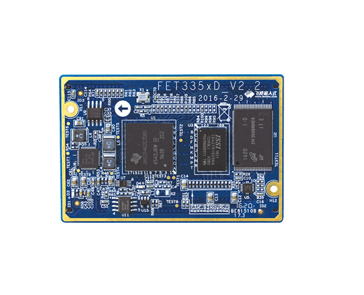
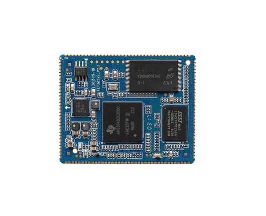
FET335xS-II system on module V3.0
The FET335xS SoM V2.2 CPU uses the same, the operating frequency of 800MHz, the 600MHz FET335xS-II power management chip is 650250, there is no voltage regulation function, the SoM main frequency can only use 600MHz, the 800MHz FET335xS uses the power management chip 65217, there are Voltage regulation function, 800MHz PCB pins are different, there are 3 different pins, other fully compatible schematic power management chips are different, others are the same
Attach the method to modify the main frequency of FET335xD and FET335xS:
The CPU frequency can be achieved by modifying the file system /etc/init.d/qt.sh script. The main frequency is set as follows, and the following code part in the script can be modified.
Set the main frequency of the CPU, save the script after setting, and execute the sync command. The way is as follows:
BOARDNAME='cat /proc/boardname'
if [ $BOARDNAME != "OK335xS2" ]; then
amixer cset name='PGA Capture Volume' 75%,75% >/dev/null
#set cpu freq from default 720M to MAX Hz
CPUMAXFREQFILE=/sys/devices/system/cpu/cpu0/cpufreq/scaling_max_freq
if [ -e $CPUMAXFREQFILE ]; then
MAXFREQ=$(cat $CPUMAXFREQFILE)
echo $MAXFREQ > /sys/devices/system/cpu/cpu0/cpufreq/scaling_setspeed
4. Test situation about FET335xD bus
(1) The support of each type of SBC to the bus
Single-board computer model bus function multiplexing OK335xD
FET335xD Gpmc bus, 16-bit data bus, 12-bit address bus can separately provide routines for communicating with ferroelectric memory (currently provided as a temporary mirror)
OKMX6UL-C baseboard EBI BUS 16-bit parallel bus is not recommended to use the bus, too many pins are multiplexed and the baseboard does not lead out the bus.
OKMX6Q-C/6DL-CEBI BUS 27-bit address bus, 32-bit data bus software manual has test scripts. However, the EMI clock is not turned on by default on the backplane, and the pins are not multiplexed as EMI. If you want to test: Refer to the software manual EMI interface test chapter. Write or read data through a script, and use an oscilloscope to measure the EMI bus signal to view the timing.
FET6818-C
The maximum data bus width of OK4418/6818-C2: 16 bits, and the maximum address bus number is 17 bits. Nor flash is welded on the bottom plate of C2, which verifies the read and write process of the bus. There are also double-row needle sockets on the baseboard, and the DuPont line is inserted to connect to the FPGA. Facilitate customer verification. (The driver is not open source, the test process is open source) Multiplexed serial port on C, PWM, touch, user buttons, and some functions affect the interruption of capacitive touch, I2C of HDMI, PWM of LCD, SDIO, WIFI, camera. These can be replaced by IO replacement, and it is not considered to completely affect these functions. C2 has no multiplexing.
OK5718-CGPMC supports 8-bit/16-bit data bus width, supports up to 28 address lines and supports up to 8 chip select lines. The software manual also introduces how to set the bus timing method.
(2) What devices can be connected to the bus
- Ferroelectric memory
- FPGA
- DSP
- Other
(3) FETMX6UL-C supports data address bus (16-bit data, 27-bit address) multiplexing is serious, it is not recommended to use. reason:
- 1) Address 0-7 and camera data line 0-7 pins are multiplexed;
- 2) Address 8-15 and NAND data line 0-7 pins are multiplexed;
- 3) Addresses 16-26 are multiplexed with NAND control lines, 6 lines of SD card, and 2 lines of network port 2;
- 4) Multiplexing of data lines 0-15 and LCD data lines 8-23;
- 5) The control line and the NAND line, the camera line, the network port 2, and the network port 1 are multiplexed.
Multiplexing occupies the main port line, it is not recommended to use external bus for FETMX6UL-C
(4) What is the form of the bus driver provided by Forlinx and can users use it directly? Is there a routine?
Answer: To debug the bus driver, you need to debug the timing according to the device connected to the bus. For example, Forlinx FET335xD provides a bus driver, and the engineer used FRAM as an example to test, so the driver of the FET335xD bus is debugged with the timing of FRAM. If the customer wants to connect to the FPGA, the driver needs to be re-modified to adapt to the timing of the FPGA. Application example Mainly realize the read and write of the device.
5. The description of the two file systems on the FET335x series SoM
Two filesystems are currently supported: ubi and yaffs.
- 1. The ubi version is divided into 256MB NandFlash version and 1GB NandFlash version, and the program is selected according to the size of the SoM NandFlash.
- 2. The adaptive 256MB NandFlash version and the 1GB NandFlash version of the yaffs version, it is recommended that the 1GB NandFlash version be the best to program the yaffs version.
- 3. Comparison of programming process: UBI: Burning image time: 2 minutes 16S.
Yaffs: Burning image time: 6 minutes 4S,
Note: For boards with different configurations, the programming time will vary by a few seconds. Users can choose the corresponding file system according to their actual needs!
6. About FET335x series SoM support for RGB 565/888
The FET335xD SoM supports RGB888, but the baseboard does not. The corresponding single-board computer comes standard with RGB565 software.
If you do not use the upper 8 bits of the GPMC bus (GPMC_D8-15), you can redesign the baseboard hardware to implement RGB888, and the corresponding software driver also needs to be modified. Please refer to the OK335xS SBC driver.
OK335xS: The system on module and baseboard, LCD screen and software driver are all RGB888.
Dear friends, we have created an exclusive embedded technical exchange group on Facebook, where our experts share the latest technological trends and practical skills. Join us and grow together!