FET-MX91xx-C System on Module Based on NXP i.MX91xx Processor
The FET-MX91xx-C is a high-performance System on Module (SoM) / Computer on Module built around NXP’s next-generation i.MX91xx series Cortex-A55 processors, delivering speeds up to 1.4GHz. Designed for industrial and embedded applications, this SoM offers a rich set of peripheral interfaces including 8x UART, 2x Ethernet, 2x USB 2.0, and 2x CAN-FD.
This module is pin-to-pin compatible with Forlinx's i.MX93 SoMs, allowing customers to easily migrate or scale their applications across different performance levels and price points, making it ideal for space-constrained, long-life embedded applications such as EV charging stations, HMIs, smart home and building automation, and industrial gateway s.
NXP i.MX91xx SoM Key Features:
- Powered by NXP i.MX91xx Cortex-A55, up to 1.4GHz – high efficiency, low power.
- Rich industrial interfaces: 8x UART, 2x GbE, 2x USB2.0, 2x CAN-FD.
- Compact 48mm × 33mm design – easy integration into space-limited systems.
- Pin-compatible with i.MX93 SoMs – flexible performance and cost scaling.
- -40°C to +85°C wide temperature range – industrial-grade reliability.
- 15-year longevity support by NXP – ideal for long-lifecycle products.
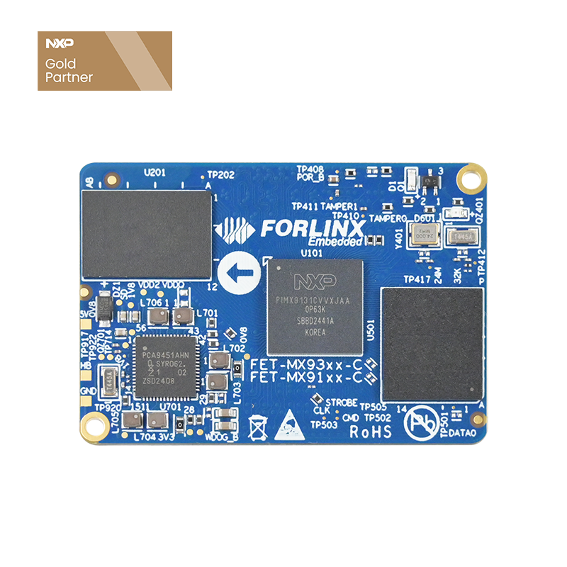
FET-MX91xx-C SoM
New Generation Linux Controller
i.MX93x VS i.MX91x
i.MX91x and i.MX93x both belong to i.MX9 series processor family,
but i.MX91x has more streamlined configuration and lower cost compared to i.MX93x.
Multiple Peripheral Interfaces-Easy to Expand
15-year Guaranteed Longevity
The i.MX91x series has been added to NXP's long-term supplying product program, with a 15-year longevity guarantee.
Wide Applicability
▊ NXP i.MX91 SoM & SBC Video
Forlinx's FET-MX91xx-C SoM & SBC based on NXP i.MX91 series
▊ Hardware Features
|
FET-MX91xx-C SoM Features |
|
|---|---|
|
CPU |
NXP i.MX91x MPU: 1×Cortex-A55@ 1.4GHz |
|
RAM |
1GB LPDDR4 |
|
ROM |
8GB eMMC |
|
Voltage input |
DC 5V |
|
Operating temperature width |
-40℃ ~ 85℃ |
|
Package |
Board-to-board connector(2*100-pin, 0.4mm pitch, combined height 1.5mm) |
|
Dimensions |
33mm x 48mm |
|
OS version |
Linux |
|
Specifications |
||
|---|---|---|
|
Interface |
QTY |
Spec. |
|
LCD |
1 |
Parallel RGB888, up to 1366×768p60 or 1280×800p60 |
|
Ethernet |
≤2 |
2x RGMII Transmission rate 10/100/1000 Mbps, complies with IEEE 802.3 |
|
UART |
≤8 |
Baud rate up to 5Mbps Supports serial data transceiver configuration, including programmable parity bit |
|
CAN-FD |
≤2 |
Supports CAN-FD and CAN 2.0B |
|
USB |
≤2 |
Two USB2.0 controllers integrated with PHY |
|
SD |
≤1 |
Complies with SD3.0 Supports SDR up to 200MHz and DDR up to 50MHz |
|
SDIO |
≤1 |
SDIO3.0 |
|
SAI |
≤3 |
A Synchronous Audio Interface (SAI) is available SAI1 supports 2 lanes, SAI2 supports 4 lanes, and SAI3 supports 1 lane Support full-duplex serial with frame synchronization, such as I2S, AC97, TDM and codec/ DSP |
|
PDM |
1 |
24-bit, supports linear phase response and AOP MIC |
|
Camera |
1 |
8-bit parallel camera interface |
|
SPI |
≤8 |
Supports to configure master or slave mode |
|
I2C |
≤8 |
Rating up to 100Kbit/s in standard mode, and 400Kbit/s in fast-speed mode, 1000Kbit/ s in enhanced fast-speed mode, 3400Kbit/s in high-speed mode, and 5000Kbit/s in super fast speed mode |
|
I3C |
≤2 |
2 Improved I3C; Support 400Kbit/s fast mode and 1000Kbit/s fast mode enhanced version, and backward compatible with I2C Support up to 12.5M clock rate, support HDR-DDR mode |
|
ADC |
≤4 |
12-bit 4-lane 1MS/s ADC |
▊ Carrier Board
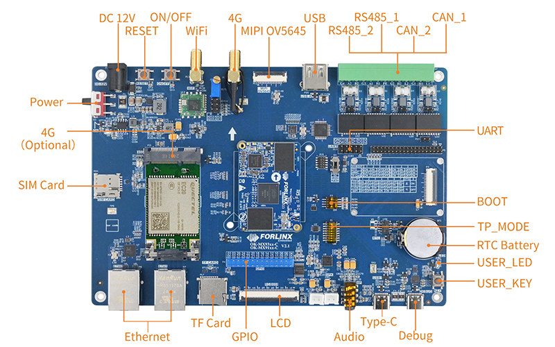
OK-MX91xx-C Single Board Computer
To minimize your development workload, we can provide starter kits that can be used as complete development platforms for evaluation and application development.
The OK-MX91xx-C single board computer from Forlinx is based on NXP's new generation i.MX91xx series and adopts a separate SoM+carrier board design. It supports 8xUART, 2xEthernet, 2xUSB2.0, 2xCAN-FD bus, and other common interfaces. And it's compatible with Folinx’s newly launched
i.MX93x series, and supports Linux system. With an open system architecture design, it can provide technical information for your secondary development.
▊ Accessories
Please click here to get more information about the supported modules and accessories.
Order Inquiry
Fill out the form below for volume pricing or technical specifications. We'll get back to you within 24 hours.
▊ How To Buy
1. Order Online
We have an online store on Alibaba, please contact us for details.
2. Order Offline
Please send your inquiry to [email protected];
3. Payment Terms
100% T/T in advance.
▊ Shipment
1. Delivery: Goods will be shipped by express upon the receipt of the payment;
2. Lead time: Goods will be shipped out within five working days for sample orders and 6 weeks for bulk orders;
3. Shipping charge: Buyers should bear the shipping cost.
▊ Other Forlinx Hot Products
Architecture: 2*A55+M33
Frequency: 1.5GHz
RAM: 1GB LPDDR4
ROM: 8GB eMMC
System: Linux 5.15.52
Architecture: 4*A53+M7
Frequency: 1.6GHZ
RAM: 2GB/4GB LPDDR4
ROM: 16GB eMMC
System: Linux5.4.70, Android 11
Architecture: 1xCortex-A55
Frequency: 1.4GHz
RAM: 1GB LPDDR4
ROM: 8GB eMMC
System: Linux