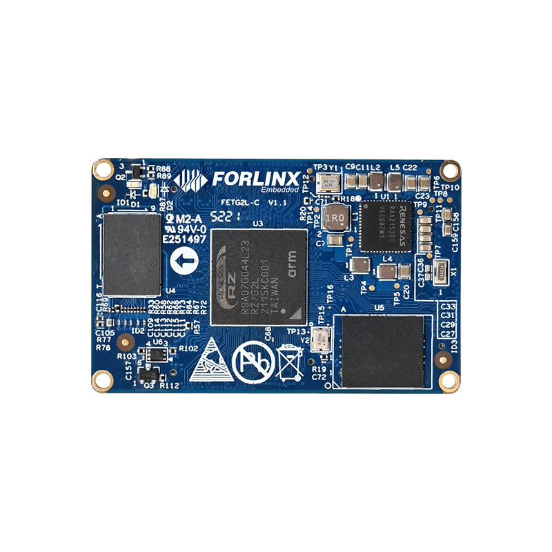
FET-G2LD-C System on Module
FET-G2LD-C System on Module(SoM) carries high-performance and ultra-efficient processor Renesas RZ/G2L. It’s heterogeneous multi-core, Cortex-A55, 1.2GHz, and integrates a MCU Cortex-M33, 200MHz. FET-G2LD-C SoM has a GPU Mali-G31 500MHz and supports a variety of display interfaces. It has rich functional interface resources, like multi-channel UART, Ethernet, CAN-FD, etc. It is applicable to industrial, medical, electric power, transportation and other pan-industrial application scenarios.
Industrial Grade, Applicable to High-Low Temperature
All components of FET-G2LD-C SoM are industrial-grade temperature, including CPU, RAM, ROM,
resistors, capacitors, inductors, connectors, operating temperature -40°C~+85°C. Thus it can easily cope with various harsh scenarios.
Super Long Life Cycle, Go Well Beyond Hardware
RZ/G2L has a 10-year+ life cycle guarantee,
and its Linux kernel is the super long-term support (SLTS) Kernel maintained by CIP, escort the long life cycle of customer products.
Rich Interface Resources, Wider Application Scenarios
FET-G2LD-C SoM is very ease of use and versatility with rich peripheral interface resources,
like 2 Gigabit Ethernet controllers, 2 CAN-FD, 2 USB 2.0,
7 UART , MIPI-DSI, Parallel RGB, MIPI-CSI, DVP, SD, IIS, IIC, SPI, QSPI, PWM, ADC, etc.
Rich Multimedia Resources, Dedicated for HMI
Rich display, camera and audio interface resources to meet the requirements of HMI and image acquisition. And it has a 3D GPU and video hardware
codec VPU to improve HMI experience; VPU hardware codec supports H.264 1920x1080x30fps Mali G31@500MHz, 3D GPU supports Vulkan, OpenGL, OpenCL.
Multi-function Timer Pulse Unit, MTU3a Enchantments
Its timer resources include 1-channel 32-bit MTU3*, 8-channel 16-bit MTU3*, 8-channel 32-bit PWM*, and 3-channel watchdog*.
The integrated Multi-Function Timer Pulse Unit 3, MTU3a, consists of eight 16-bit timer channels and one 32-bit channel.
It can realize PWM complementary input and output for encoder signal input and motor control.
Target Applications
FET-G2LD-C SoM is applicable to industry, healthcare, electric power, vehicle transportation, security, energy and chemical industry, communication, industry and so on.
OK-G2LD-C SBC Interface
OK-G2LD-C SBC consists of FET-G2LD-C SoM and carrier board. It integrates rich functional interfaces and makes product evaluation easier.
▊ Product Video
System on Module FET-G2LD-C based on Renesas RZ/G2L
▊ Spec.
|
FET-G2LD-C SoM Basic Parameters |
|
|---|---|
|
Processor |
Renesas RZ/G2L (R9A07G044Lxx) MPU Core: Arm [email protected], 1-core or 2-core MCU Core: Arm Cortex-M33@200MHz, 1-core GPU: • Arm Mali-G31 • OpenGL ES 1.1/2.0/3.1/3.2, Vulkan 1.1, OpenCL 2.0 VPU: Encoding / Decoding • H.264 / AVC (High Profile / Main Profile / Baseline Profile) • H.264 / MVC (Stereo High Profile) • up to 1920 x 1080 x 30 fps ISU: • image input up to 5M (2800×2047) • image output up to Full HD (1920×1080) • Support color format conversion • RGB / ARGB / YcbCr422 / YcbCr420 / RAW(Grayscale) |
| RAM | 2GB DDR4 |
| ROM |
QSPI NorFlash: 16MB eMMC: 16GB |
| Working Voltage | DC 5V |
| Working Temperature | -40~85℃ |
| Package | board to board connector(3*80pin Spacing 0.5mm, height 2mm) |
| Dimensions | 38mm x 60mm |
| OS | Linux4.19 |
|
FET-G2LD-C SoM Function Parameter |
|||
|---|---|---|---|
| Interface | QTY | QTY | |
| MIPI-DSI | 1 |
One 4-lane MIPI display serial interface, each lane supports up to 1.5 Gbps Up to 1920 x 1080@60fps |
Pin multiplexing interface, choose one |
| Parallel RGB | 1 | One parallel display interface, up to WXGA (1280x800@60fps) | |
| MIPI-CSI | 2 | two 4-lane MIPI camera serial interfaces, 4lane up to 4000Mbps | Pin multiplexing interface, choose one |
| DVP | 2 |
Support ITU-R BT.656 (support Interlace, YcbCr422 8-bit/10-bit) Support HD, 30 fps (YCbCr422 Interleave), 60 fps (YCbCr422 Y/CbCr separate data, binary data) Maximum input pixel clock: 74.25MHz Input data format: YcbCr422 8-bit / 10-bit; Binary data 16-bit. |
|
| USB HOST | 1 | USB 2.0 (up to 480 Mbps) | |
| USB OTG | 1 | USB 2.0 (up to 480 Mbps) | |
| QSPI | 1 | maximum clock frequency: 50 MHz (Quad-SPI DDR), 66 MHz (Quad-SPI SDR), 100 MHz (Octal-SPI, HyperFlash) | |
| SD | 1 | 1-bit / 4-bit SD bus, support default, high speed, UHS-I/SDR50, SDR104 transmission mode | |
| Audio | ≤4 | Support I2S, mono, tdM mode | |
| Ethernet | ≤2 |
1000/100/10 Mbps IEEE802.3 PHY RGMII and IEEE802.3 PHY MII |
|
| CAN FD | ≤2 | CAN-FD ISO 11898-1 (CD2014), up to 4Mbps | |
| I2C | ≤3 |
Support master mode and slave mode, support multi-master operation, support timeout detection Support 7bit and 10bit slave address format |
|
| UART | ≤5 |
Supports separate 16-byte FIFO registers for transmit and receive Support full duplex mode Supports modem control functions (channels 0, 1 and 2 in asynchronous mode) |
|
| UART | ≤2 |
without FIFO without FIFO Support modem control function Selectable Clock Synchronous Mode, Asynchronous Mode or Smart Card Mode Encode and decode IrDA communication waveforms according to IrDA 1.0 (on channel 0) |
|
| SPI | ≤3 |
Supports master mode and slave mode Programmable bit length, clock polarity, clock phase selectable up to 50 Mbps |
|
| MTU3 | ≤9 |
Multi-function Timer Pulse Unit 3 Supports Toggle, PWM, Complementary PWM and Reset Synchronous PWM modes Support dead time compensation counter function Digital filter function supporting input capture and external count clock pins |
|
| GPT | ≤8 |
General PWM Timer Support counting up or down (sawtooth wave), counting up or down (triangle wave) Independently selectable for each channel, 2 input/output pins per channel |
|
| WDT | 3 |
Watchdog Timer WDT CH0: WDT to check the operation of Cortex-A55-CPU Core0 WDT CH1: WDT to check the operation of Cortex-A55-CPU Core1 WDT CH2: WDT to check the operation of Cortex-M33 CPU |
|
| ADC | 8 |
Resolution: 12-bit Input voltage: 0V~1.8V Conversion Time: 1us Operation Mode: Single Scan/Continuous Scan A/D conversion start condition: · Software trigger · Asynchronous trigger (support external trigger) · Synchronous triggering (MTU and PWM timers) |
|
| JTAG | 1 | debug | |
| OK-G2LD-C SBC Function Parameter | ||
|---|---|---|
| Interface | QTY | Spec. |
| MIPI DSI | 1 |
The carrier board leads out 4 lane MIPI_DSI through FPC socket; default adaptive Forlinx 7-inch MIPI screen, resolution 1024 x 600@30fps Reserve support Forlinx MIPI-DSI to LVDS & HDMI module; |
| MIPI CSI | 1 |
Lead out through 26Pin FPC socket and 2 x 10Pin 2.0mm sockets; Support OV5645, up to 2592X1944 |
| USB Host | 2 | Two USB 2.0 extended by the hub (up to 480 Mbps) |
| USB OTG | 1 | USB2.0 lead out through USB Type-C( up to 480 Mbps) |
| Ethernet | 2 | 10/100/1000Mbps, RJ-45 |
| WiFi | 1 |
Module: RL-UM02WBS-8723BU-V1.2 WiFi: IEEE 802.11b/g/n 2.4GHz Bluetooth: BT V2.1/BT V3.0/BT V4.0 |
| Bluetooth | 1 | |
| 4G | 1 | Support 4G module EC20 by default |
| QSPI | 1 | One QSPI Flash chip on QSPI1 to store user data |
| TF Card | 1 | The carrier board leads out SD signal through TF card holder, which can mount TF Card |
| Audio | 1 |
WM8960 default onboard; Support headphone output and MIC input, integrated on one 3.5mm headphone jack; Support two 1W8Ω speaker output, lead out through XH2.54 white terminal |
| CAN | 2 | CAN-FD with Electrical isolation |
| RS485 | 1 | Automatic control of sending and receiving direction, with electrical isolation |
| I2C | 3 | to mount audio, RTC, camera and other equipment on carrier board |
| PWM | 1 | adjust backlight brightness |
| RTC | 1 | Independent RTC chip onboard. The time will be recorded by button battery when carrier board is powered off. |
| SCIF(UART) | 1 | Lead out through 2.54mm pins |
| SPI | 3 | Lead out through 2.54mm pins |
| ADC | 8 |
Lead out through 2.54mm pins ADC_CH4 is additionally connected to a sliding rheostat to facilitate user debugging |
| JTAG | 1 | Lead out through 1.27mm pins |
▊ Download
Catalog:
Forlinx Catalog Manual
Product Brief:
FET-G2LD-C SoM and OK-G2LD-C SBC Introduction
▊ Accessories
Please click here to get more information about the supported modules and accessories.
| Optional Module | ||
|---|---|---|
| 4G Module | OV5645 Camera | 7-inch MIPI Screen |
| 1 | 1 | 1 |
|
|
|
|
Technical Support
Forlinx provides software resources including kernel and driver source code, together with detailed user manual, schematic documentations to help customer start their development rapidly.
Request a Quote
Fill out the form below for volume pricing or technical specifications. We'll get back to you within 24 hours.
▊ How To Buy
1. Order Online
We have an online store on Alibaba, please contact us for details.
2. Order Offline
Please send your inquiry to [email protected];
3. Payment Terms
100% T/T in advance.
▊ Shipment
1. Delivery: Goods will be shipped by express upon the receipt of the payment;
2. Lead time: Goods will be shipped out within five working days for sample orders and 6 weeks for bulk orders;
3. Shipping charge: Buyers should bear the shipping cost.
▊ Related News
- New Arrival | Forlinx Released FET-G2LD-C SoM
- Forlinx RZ/G2L System on Module and SBC Evaluation
- Development Board OK-G2LD-C Tests of Storage Read/Write Speed and Gigabit Ethernet Bandwidth
▊ Other Forlinx Hot Products
Architecture: 2*A55+M33
Frequency: 1.2GHz
RAM: 1GB/2GB DDR4
ROM: 16MB QSPI NorFlash,8GB/16GB(Optional)
System: Linux4.19
Architecture: 2*A55+M33
Frequency: 1.5GHz
RAM: 1GB LPDDR4
ROM: 8GB eMMC
System: Linux
Architecture: 4*A53+M7
Frequency: 1.6GHZ
RAM: 2GB/4GB LPDDR4
ROM: 16GB eMMC
System: Linux5.4.70+Qt5.15, Android 11