


OK3568-UP4 Development Board | Rockchip RK3568 Industrial AIoT SBC
The OK3568-UP4 Development Board is a versatile evaluation platform built for high-performance AIoT and industrial edge computing applications. Powered by the Rockchip RK3568 platform, this single board computer seamlessly integrates an expansive carrier board with the modular FET3568-UP4 SoM. Featuring 1 TOPS NPU inference, dual Gigabit Ethernet, PCIe 3.0, SATA 3.0, and triple-independent-display support (HDMI 4K, LVDS, MIPI-DSI, eDP), the OK3568-UP4 provides an ideal turnkey environment for prototyping smart gateways, machine vision, and industrial HMI systems.
OK3568-UP4 Development Board
Skip the complexity of hardware design with the OK3568-UP4 Development Board. This production-ready platform combines a proven SoM + Carrier architecture,
allowing you to bypass low-level circuitry and focus entirely on your software.
Seamlessly transition from initial concept to mass production with minimal risk and comprehensive Linux support.
What is the UP4 Package?
UP4 is a standardized System-on-Module (SoM) footprint defined by Forlinx Embedded.
"UP" stands for Universal Package, and "4" indicates its 40mm × 40mm physical form factor.
The package features a 487-pin hybrid LCC (Castellated Holes) + LGA (Land Grid Array) layout.
Core Advantages of UP4 SoM
The UP4 System-on-Module (SoM) series establishes an open hardware standard for seamless interchangeability.
By unifying physical dimensions, footprint design, and pin assignments, it significantly reduces embedded development complexity and project risk.
Flexible Supply Chain Options
The SoMs can integrate processors from different vendors, reducing chip supply risks.
Powerful A55 with NPU
FET3568-UP4 SoM is equipped with quad-core 64-bit Cortex-A55 processor with built in NPU based on advanced 22nm process technology,
running at up to 2.0GHz, and plenty of high-speed peripheral interfaces are available.
Multiple Display Interfaces: Realize Three-Screen Heterogeneous Display
HDMI2.0, eDP, LVDS, RGB Parallel and MIPI-DSI are all well supported, besides,
it supports three displays simultaneously output up to 4K,
which is preferable and applicable for PDA, cash register, multi-screen advertising machine, karaoke machine, electronic bus stop board, self-service machine, etc.
Rich High-Speed Interfaces: Expand Functionality and Connect More Efficiently
Equipped with 3 PCIe, 4 separate USB, 3 SATA controllers,
and 2 builtin GMAC can support RGMII/ SGMII/ QSGMII(2MAC) to expand dual Gigabit Ethernet ports.
Compatible with RTOS, Reduces Latency
FET3568-UP4 SoM is equipped with quad-core 64-bit Cortex-A55 processor with built in NPU based on advanced 22nm process technology,
running at up to 2.0GHz, and plenty of high-speed peripheral interfaces are available.
Pin-Compatible UP4 Family Overview
Introducing the Forlinx Pin-Compatible UP4 Family
▊ Hardware Features
| FET3568-UP4 / FET3568J-UP4 System on Module Basic Features | ||
|---|---|---|
| Processor | SOC | Rockchip RK3568B2 / RK3568J |
| CPU | Quad-core [email protected] / 1.8GHz | |
| NPU | 1TOPS, supporting INT8/INT16/FP16/BFP16 mixing operation | |
| GPU | Mali-G52-2EE; OpenGL ES 1.1, 2.0, 3.2, Vulkan 1.0, 1.1, OpenCL 2.0 | |
| VPU (Decode) |
Hardware Decoding: • H.264, H.265, VP9:up to 4096x2304@60fps • VP8:up to 1920x1088@60fps • VC1, MPEG-4, MPEG-2, MPEG-1:up to 1920x1088@60fps • H.263:up to 720x576@60fps |
|
| VPU (Encode) |
Hardware Encoding: • H.264/AVC, H.265/HEVC:up to 1920×1080@60fps |
|
| RAM | 1GB / 2GB / 4GB / 8GB LPDDR4X | |
| ROM | 8GB / 16GB / 32GB / 64GB eMMC | |
| Operating Temperature | -40℃ ~ +85℃ / 0℃ ~ +80℃ | |
| Working Voltage | DC 5V | |
| Connection | LCC + LGA (487 pins, pin center pitch of stamp hole is 1mm, single pin size: 0.7 * 0.6mm, ball pitch of LGA is 1.27 mm, single ball diameter is 0.8mm) | |
| Dimension | 40mm × 40mm | |
| OS | Linux5.10+Qt5.15.8 | |
| System Flashing Method |
• SD card • USB OTG |
|
| FET3568-UP4 / FET3568J-UP4 System On Module Function Parameters | ||||
|---|---|---|---|---|
| Function | Max Number | Maximum Capacity Parameter | UP4 Resources | UP4 Parameter |
| MIPI-DSI | 2 | 2 x 4 - lane MIPI display serial interfaces, supporting MIPI V1.2 version. The maximum resolution of a single channel is 1920×1080@60Hz, and the maximum resolution of dual channels is 2560×1600@60Hz. | 1 | 1 x 4 - lane MIPI display serial interfaces, supporting MIPI V1.2 version. The maximum resolution of a single channel is 1920×1080@60Hz, and the maximum resolution of dual channels is 2560×1600@60Hz. |
| HDMI | 1 | Supports HDMI 2.0 with resolutions up to 1080p @ 120Hz or 4096 × 2304 @ 60Hz | 1 | Supports HDMI 2.0 with resolutions up to 1080p @ 120Hz or 4096 × 2304 @ 60Hz |
| LVDS | 1 | Single lane(4 lanes)supports 1280×800@60Hz | 1 | Single lane(4 lanes)supports 1280×800@60Hz |
| eDP | 1 | 1 x 4-lane eDP display interface, supporting eDP V1.3, and the maximum resolution is 2560×1600@60Hz | 1 | 1 x 4-lane eDP display interface, supports eDP V1.3, and the maximum resolution is 2560×1600@60Hz |
| RGB | 1 | Supports RGB 888, maximum resolution 1280 x 800 | 1 | Supports RGB 888, maximum resolution 1280 * 800 |
| Camera | 3 | Supports 1 x 4 Lanes MIPI-CSI,2 x 2Lanes MIPI-CSI | 2 | Supports 2 x 2Lanes MIPI-CSI |
| IIS | ≤4 | 1×8ch I2S/TDM,2×2ch I2S,1×8ch PDM | / | |
| Audio | 1 |
Built - in codec, which directly outputs audio analog signals with a sampling rate ranging from 48KHz to 192KHz: Mono speaker, class - D, 1.3W; Stereo headphone output with a 32Ohm load; one differential MIC input. |
1 |
Built - in codec, which directly outputs audio analog signals with a sampling rate ranging from 48KHz to 192KHz: Mono speaker, class - D, 1.3W; Stereo headphone output with a 32Ohm load; one differential MIC input. |
| SDIO | ≤2 | SDIO 3.0 with up to 104MB/S data throughput | 2 | SDIO 3.0 with up to 104MB/S data throughput |
| Ethernet | ≤2 | 2 x GMAC, RGMII/RMII interface are routed out | 2 | 2 x GMAC, RGMII/RMII interface are routed out |
| USB 2.0 | 2 | USB 2.0 Host, independent port, not multiplexed with USB 3.0 | 2 | USB 2.0 Host, independent port, not multiplexed with USB 3.0 |
| USB 3.0 | 2 |
1 x USB 3.0 Host port, which can be used independently as a USB 2.0 Host; 1 x USB 3.0 OTG port, which can be used independently as a USB 2.0 OTG. |
2 |
1 x USB 3.0 Host port, which can be used independently as a USB 2.0 Host; 1 x USB 3.0 OTG port, which can be used independently as a USB 2.0 OTG. ; |
| SATA | ≤3 | SATA 3.0 up to 6.0 Gb/s with eSATA support | / | |
| PCIe2.1 | ≤1 | PCIe 2.1×1,up to 5.0Gbps,RC mode | 1 | PCIe 2.1×1,up to 5.0Gbps,RC mode |
| PCIe3.0 | ≤2 | PCIe 3.0,1×2Lanes or 2×1Lane, up to 8.0 Gbps per Lane; 1Lane supports Root Complex (RC) mode only; 2 Lanes supports Root Complex (RC) and End Point (EP) model. | 1 | PCIe 3.0, 1x2Lanes, up to 8.0 Gbps per Lane; 1Lane supports Root Complex (RC) mode only; 2Lanes supports Root Complex (RC) and End Point (EP) model. |
| UART | ≤10 | Up to 4Mbps | 3 | Up to 4Mbps |
| CAN | ≤3 | Supports CAN2.0 B up to 1Mbps | 2 | Supports CAN2.0 B up to 1Mbps |
| SPI | ≤4 | Support master & slave mode, with configurable software | / | |
| I2C | ≤5 | Supports 7bits and 10bits address modes up to 1 Mbit/s | 3 | Supports 7bits and 10bits address modes up to 1 Mbit/s |
| PWM | ≤16 | 32bits timer/counter | 4 | 32bits timer/counter |
| FSPI | ≤1 | Supports serial NOR Flash/NAND Flash and Boot | / | |
Note*: The maximum number of parameters in the table is the theoretical value of hardware design or CPU; The number of interface resources defined by UP4 in the table is the maximum number supported by the UP4 universal package.
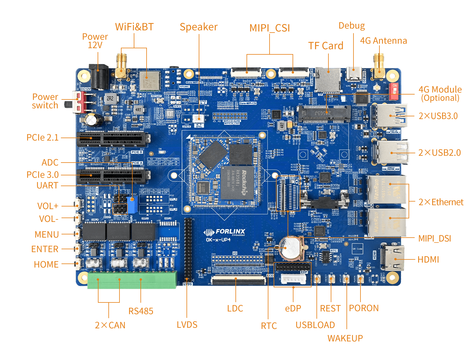
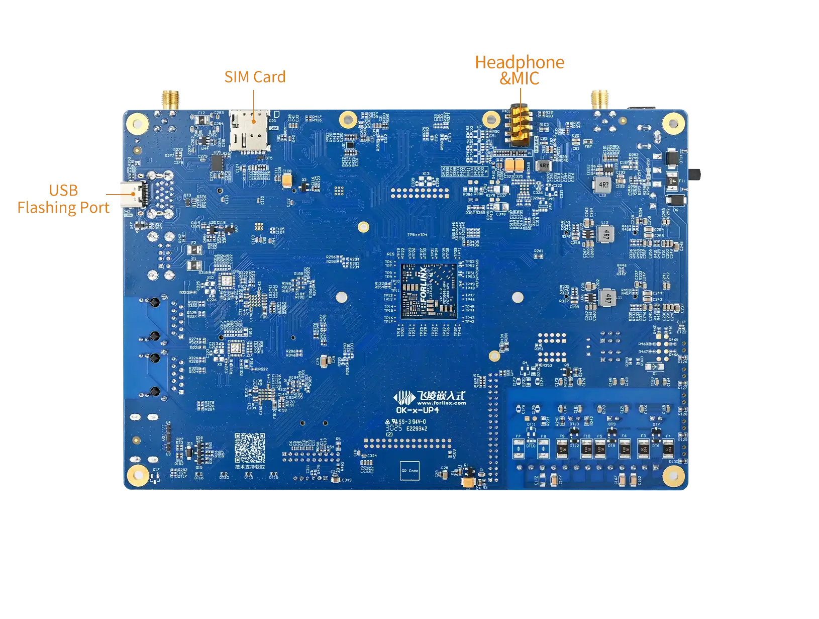
▊ Carrier Board
|
|
| OK3568-UP4 / OK3568J-UP4 Development Board Function Parameters | ||
|---|---|---|
| Function | Quantity | Parameter |
| WiFi & Bluetooth | 1 | Single antenna 2.4G & 5GHz Wi-Fi Dual-band 1X1 802.11ac + Bluetooth 4.2 |
| Audio | 1 | Mono speaker connector, class-D, 1.3 W; Stereo headphone output, 32 Ohm load; Headphone recording + on-board MIC recording |
| MIPI-CSI | 3 | Led out from the FPC socket, 4lane+ 2lane+ 2lane |
| TF Card | 1 | Data rate up to SDR104; |
| 4G | 1 | Supports 4G modules with a miniPCIE interface, integrating USB2.0 communication signals. |
| UART Debug | 2 | Integrated into a single Type-C port, enabling connection to a PC for debugging. |
| USB3.0 | 2 | USB_A can switch the master-slave mode and perform USB programming, while USB_C only supports the master mode. |
| USB2.0 | 2 | 1 x USB-D native USB2.0 and 1 x USB-HUB are led out |
| Ethernet | 2 | 2 x Gigabit ports led out via a standard RJ45 socket |
| HDMI | 1 | Supports HDMI 2.1 resolution up to 4096× 2304 @ 60Hz |
| EDP | 1 | Supports eDP 1.3 resolution up to 2560× 1600 @ 60Hz |
| MIPI-DSI | 1 | 4-lane MIPI-DSI, supporting capacitive touch screen and backlight brightness adjustment. The maximum resolution of a single channel is 1920 × 1080@60Hz, and the maximum resolution of dual channels is 2560×1600@60Hz. |
| RTC | 1 | On-board CR1220 battery, keep going when power is off |
| LCD | 1 | RGB888 interface, supporting capacitive touch and resistive touch, and allowing backlight brightness adjustment. The maximum resolution is 1280×800. |
| LVDS | 1 | 4-lane LVDS, supporting capacitive touch screen and backlight brightness adjustment, up to 1280×800@60Hz |
| RS485 | 1 | Electrical quarantine |
| CAN | 2 | Supports CAN2.0B, electrical quarantine |
| ADC | 3 | Led out from the pin header and can be connected to the on-board sliding rheostat |
| UART | 1 | 5 x UART, led out through pin headers. |
| KEY ADC | 5 | 5 keys are led out via 1 x LRADC |
| PCIe | 2 | PCIe _ B 2.1, can only do RC mode, PCIe _ A 3.0, can do EP and RC mode |
▊ Accessories
Please click here to get more information about the supported modules and accessories.
▊ Documentation
Reference Manuals
Hardware Related
Product Datasheet
User Guide
Carrier Board Schematic
Carrier Board PCB
SoM Pinmux
Software & BSP
OS Image
Testing Demo
Source Code
Manual
Request a Quote
Fill out the form below for volume pricing or technical specifications. We'll get back to you within 24 hours.
▊ Ordering Information
1. Online Channels: We have an online store on Alibaba and DigiKey. Please contact us for details.
2. Direct Inquiry: For bulk orders, please email our sales team at [email protected].
3. Payment Method: Standard terms: 100% T/T (Telegraphic Transfer) in advance.
1. Dispatch Method: Orders are shipped via international express upon receipt of payment.
2. Lead Time: 5 working days for samples; 6 weeks for bulk orders.
3. Shipping Policy: Shipping and handling fees are the responsibility of the purchaser.
▊ Forlinx Recommended Products
Architecture: Octa-core ARM Cortex-A55 (4+4 cluster)
Frequency: CPU 1.8GHz/1.4GHz | RISC-V 200MHz | DSP 600MHz
RAM: 2GB/4GB LPDDR4
ROM: 16GB / 32GB eMMC
Architecture: 4x [email protected]+RISC-V@600MHz
Frequency: 1.6GHZ
RAM: 1GB/2GB/4GB LPDDR4
ROM: 8GB/16GB/32GB eMMC
Architecture: 4×Cortex-A53
Frequency: [email protected]
RAM: 1GB/2GB LPDDR4
ROM: 8GB/16GB eMMC
Architecture: 2*A55+M33
Frequency: 1.7GHz
RAM: 1GB LPDDR4
ROM: 8GB eMMC