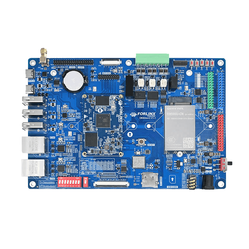
OK62xx-C Single Board Computer
OK62xx-C single board computer(SBC) is based on TI Sitara™ AM62x series(AM6254) industrial SoC applicable for single-core AM6251, dual-core AM6252 and quad-core AM6254, ARM Cortex-A53, 1.4GHz. Its structure is SoM + carrier board structure, board-to-board connection, easy to plug and unplug. The SoM size is 60mm*38mm.
This development board is to evaluate SoM FET62xx-C, which can be used as a development platform or as an end item. It has rich peripheral interface resources, including two Gigabit Ethernet(support TSN), USB 2.0, LVDS, RGB parallel, UART, OSPI, CAN-FD, Camera, Audio.
|
1GB DDR4+8GB eMMC |
2GB DDR4+8GB eMMC |
1/2GB DDR4+8GB eMMC |
||||
|
|
|
|
||||
| Product | CPU Cores | Frequency | RAM(DDR4) | ROM(eMMC) | Working Temperature | OS |
| FET6231-C | Single core | 1.0 GHz | 1GB | 8GB | -40℃ ~ 85℃ | Linux 6.1.33 |
| FET6232-C | Dual core | 1.4 GHz | 2GB | 8GB | -40℃ ~ 85℃ | Linux 6.1.33 |
| FET6254-C | Quad core | 1.4 GHz | 1GB | 8GB | -40℃ ~ 85℃ | Linux 6.1.33 |
| FET6254-C | Quad core | 1.4 GHz | 2GB | 8GB | -40℃ ~ 85℃ | Linux 6.1.33 |
OK62xx-C SBC
Cortex-A53 featuring AM62 series processors with running speed at up to 1.4GHz and various peripheral interfaces
such as Ethernet with TSN, USB2.0, LVDS, RGB parallel, UART, OSPI, CAN-FD, camera, audio, etc.
FET62xx-C is compatible with single core AM6231, dual-core AM6232 and quad-core AM6254 pin2pin, providing maximum scalability to users.
TI AM62X: Your Next-Generation HMI Solution
AM62x is a new generation of MPU family which is more scalable and extensive than AM335x,
it's designed to address the requirements and goals of Industry 4.0 for factories of the future.
Heterogeneous Multi-core, More security
AM62x is a hybrid processor family integrated with Cortex-A53 core and Cortex-M4F core;
Cortex-M4F with dedicated device level interconnect for security.
CAN-FD Empowers Industrial Automation and Vehicle Applications
AM62x supports 3 CAN-FD up to 5Mbps connecting to industrial networking stably,
providing functional reinforcements for industrial automation and vehicle applications.
GPMC for Parallel Host Interface to An External ASIC/FPGA
AM62x is enabled with GPMC with read/ write rating up to 100MB/s; Besides,
multiple chip-selection provides maximum flexibility for multi-communicating with external peripherals.
Exclusive Triple-display Output
FET62xx-C SoM support two display controllers with different output. Exclusively, it is capable of simultaneously driving three displays.
Target Applications
The SoM could be widely used in Human Machine Interfaces (HMI), Industrial computer,
Edge computing, Retail automation, Driver Monitoring System (DMS/OMS) / In-Cabin Monitoring (ICM),Telematics Control Unit (TCU),
Vehicle to Infrastructure / Vehicle to Vehicle (V2X / V2V),3D Re-configurable automotive instrument cluster, Appliance user interface and connectivity, Medical equipment.
▊ Product Demo Video
Forlinx TI AM62x SoM / SBC support Triple-Display
▊ Hardware Features
|
FET62xx-C SoM Features |
|
|---|---|
|
Processor |
TI Sitara™ AM62x CPU:Cortex-A53 @1.0/1.4GHz MCU:Cortex-M4F@400MHz GPU:(AM6231、AM6232 NoneGPU) AXE1-16M@500MHz OpenGL 3.x/2.0/1.1 + Extensions, Vulkan 1.2 |
|
Architecture |
Up to Quad 64-bit ARM ® Cortex ®[email protected] |
|
RAM |
AM6231:1GB DDR4; AM6232:1GB/2GB DDR4; AM6254:1GB/2GB DDR4 |
|
ROM |
8GB eMMC |
|
OS |
Linux 6.1.33 |
|
Working Voltage |
DC 5V |
|
Package |
Board to board connector(4x 80-pin, 2mm combined height, 0.5mm pitch) |
|
Dimensions |
60mm x 38mm |
|
Working Temperature |
-40℃ ~ 85℃ |
|
Firmware installation |
SD / TF card U-disk USB DFU |
|
Comparison of AM62x processors and the situation of Forlinx products |
||||||
|---|---|---|---|---|---|---|
| CPU |
AM6254 |
AM6252 |
AM6251 |
AM6234 |
AM6232 |
AM6231 |
| CPU cores |
4 |
2 |
1 |
4 |
2 |
1 |
| 3D Graphics engine |
√ |
√ |
√ |
× |
× |
× |
| Does Forlinx have this product? |
√ |
× |
× |
× |
√ |
√ |
|
Specifications |
||
|---|---|---|
|
Interface |
QTY |
Spec. |
|
OLDI/LVDS |
2 |
– 1920x1080 @ 60fps for each display – 1x 2048x1080 + 1x 1280x720 – OLDI/LVDS (4 lanes - 2x) and 24-bit RGB parallel interface |
|
24-bit RGB parallel interface |
1 |
|
|
Camera Serial interface |
1 |
– MIPI CSI 1.3 Compliant + MIPI-DPHY 1.2 – Support for 1,2,3 or 4 data lane mode up to 2.5Gbps per lane |
|
Camera Serial interface |
1 |
– MIPI CSI 1.3 Compliant + MIPI-DPHY 1.2 – Support for 1,2,3 or 4 data lane mode up to 2.5Gbps per lane |
|
Ethernet |
2 |
– RMII(10/100) or RGMII (10/100/1000) – IEEE1588 (Annex D, Annex E, Annex F with 802.1AS PTP) – Time sensitive networking (TSN) support – IP/UDP/TCP checksum offload in hardware |
|
USB2.0 |
2 |
– Port configurable as USB host, USB peripheral, or USB Dual-Role Device (DRD mode) – Integrated USB VBUS detection – Trace over USB supported |
|
UART |
9 |
– 16C750-compatible – RS-485 external transceiver auto flow control support – The 48 MHz functional clock is default option and allows baud rates up to 3.6 Mbps – Stop-bit: 1, 1.5, 2 bit(s) – Parity bit: Even, odd, none |
|
SPI |
5 |
– Serial clock with programmable frequency, polarity, and phase for each channel – MCSPI Controller Clock Rates up to 50 MHz |
|
I2C |
6 |
– Supports a standard mode (up to 100 Kbps) and fast mode (up to 400 Kbps) – 7-bit and 10-bit device addressing modes |
|
McASP |
3 |
– Transmit and Receive Clocks up to 50 MHz – Up to 16/10/6 Serial Data Pins across 3x McASP with Independent TX and RX Clocks – Supports Time Division Multiplexing (TDM), Inter-IC Sound (I2S), and Similar Formats – Supports Digital Audio Interface Transmission (SPDIF, IEC60958-1, and AES-3 Formats) – Support for audio reference output clock |
|
ePWM |
3 |
Two PWM outputs (EPWMxA and EPWMxB) that can be used in the following configurations: – Two independent PWM outputs with single-edge operation – Two independent PWM outputs with dual-edge symmetric operation – One independent PWM output with dual-edge asymmetric operation Dead-band generation with independent rising and falling edge delay control |
|
eQEP |
3 |
– Input synchronization – Three stage/six stage digital noise filter – Quadrature decoder unit – Position counter and control unit for position measurement – Quadrature edge capture unit for low-speed measurement – Unit time base for speed and frequency measurement – Watchdog timer for detecting stalls – EQEP inputs (A/B/INDEX and STROBE) are available at chip level – EQEP phase error output is also available. The status of the phase error can be observed by software through the register in the CTRL_MMR0 module. |
|
eCAP |
3 |
– 4 × 32 bits event time-stamp capture registers ( through ) – 4-stage sequencer (Mod4 counter), synchronized to external events (ECAPx pin edges) – Independent edge polarity (rising / falling edge) selection for all 4 sequenced time-stamp capture events – Input capture signal pre-scaling (from 1 to 16) – One-shot compare register (2 bits) to freeze captures after 1 to 4 time-stamp events – Continuous mode capture of time-stamps in a four-deep circular buffer – Interrupt capabilities on any of the 4 capture events – Absolute time-stamp capture – Difference (Delta) mode time-stamp capture – above resources dedicated to a single input pin – When not used in capture mode, the ECAP module can be configured as a single channel PWM output |
|
GPIO |
n |
All LVCMOS I/O can be configured as GPIO |
|
CAN-FD |
3 |
– Conforms w/ CAN Protocol 2.0 A, B and ISO 11898-1 – Full CAN FD support (up to 64 data bytes) – Parity/ECC check for Message RAM – Speed up to 5Mbps |
|
SD |
2 |
– 2x 4-bit SD/SDIO interface up to UHS-I – Compliant with eMMC 5.1, SD 3.0 and SDIO Version 3.0 |
|
GPMC |
1 |
– 1× General-Purpose Memory Controller (GPMC) up to 133MHz
– Flexible 8- and 16-Bit Asynchronous Memory Interface With up to four Chip (22-bit address) – Uses BCH Code to Support 4-, 8-, or 16-Bit ECC – Uses Hamming Code to Support 1-Bit ECC
– Error Locator Module (ELM) |
|
OSPI/QSPI |
1 |
OSPI/QSPI with 166 MHz DDR / 200MHz SDR – Support for Serial NAND and Serial NOR flash devices – Up to 4 CS supported – 4GBytes memory address support – XIP mode with optional on-the-fly encryption |
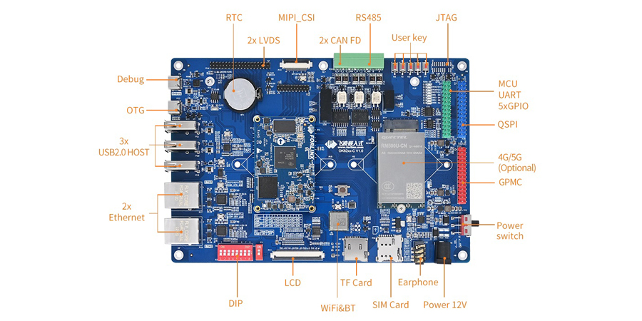
▊ OK62xx-C Features
|
|

|
Carrier board features |
|
|---|---|
|
Dimensions |
190x130mm |
|
Voltage input |
12V |
|
Working Temperature |
-40℃ ~ 85℃ |
|
Specifications |
||
|---|---|---|
|
Interface |
QTY |
Spec. |
|
LVDS |
2 |
Dual async channel(8 data, 2 clocks) up to 1920x1200p60, tested model: Forlinx 10.1’’ LVDS module with resolution of 1280x800 @ 60fps |
|
16-bit RGB parallel interface |
1 |
16-bit by FPC connector on carrier board, Tested model: Forlinx 7’’ LCD module both resistive and capacitive TP, resolution of 1024x600@ 60fps |
|
Camera Serial interface |
1 |
Forlinx camera module OV5645 up to 2592X1944 |
|
Ethernet |
2 |
10/100/1000Mbps auto-negotiation, RJ45 header |
|
USB2.0 |
4 |
3 x USB HOST 1 x USB OTG |
|
DEBUG UART |
3 |
UART0 and WKUP_UART0 are converted to USB as Type-C connector on carrier board, MCU_UART0 is available on carrier board by pin headers with pitch of 2.54mm |
|
RS485 |
1 |
Electrical isolation |
|
SPI |
1 |
MCU_SPI0 by pin headers with pitch of 2.54mm, rating up to 50 MHz |
|
I2C |
2 |
MCU_I2C0 and WKUP_I2C0 are available on carrier board by pin headers with pitch of 2.54mm |
|
GPMC |
1 |
GPMC_AD0~AD15, 16-bit data and related controlling signals, by pin headers with pitch of 2.54mm |
|
CAN-FD |
1 |
Electrical isolation, rating up to 5Mbps |
|
Audio |
1 |
1x phone output and 1x MIC input |
|
TF-CARD |
1 |
1x TF card slot, can support UHS-I standard TF card up to 104MB/s |
|
4G/5G |
1 |
M.2 Key B slot for 4G and 5G which are optional and alternative, |
|
WiFi |
1 |
On-board WiFi module AW-CM358M; |
|
BT |
1 |
|
|
JTAG |
1 |
By 2 x 10-Pin headers with pitch of 1.27mm |
|
KEY |
8 |
4 input keys for A core, and 1 input key for M core |
|
LED |
5 |
4 output LED for A core and 4 output LED for M core |
|
RTC |
1 |
on-board RTC chipset |
|
EEPROM |
1 |
2K bit, can be mounted to MCU_I2C0 or WKUP_I2C0 |
|
QSPI Flash |
1 |
128M bit, can be mounted to QSPI or MCU_SPI0 |
▊ Downloads
Catalog:
Forlinx Catalog Manual
Datasheet:
TI AM62x Series SOM and EVK brief introduction
|
Linux5.10 |
User manual, compiling guideline, kernel source code, file system, OS image, VM ubuntu image, SD card tool, USB OTG tool, QT demos and source code |
| Hardware | User manual, carrier board schematic, carrier board PCB(AD), datasheet, carrier board and SoM DXF files, pinmux sheet |
▊ Accessories
Please click here to get more information about the supported modules and accessories.
▊ Technical Support
Forlinx provides software resources including kernel and driver source code, together with detailed user manual, schematic documentations to help customer start their development rapidly.
Request a Quote
Fill out the form below for volume pricing or technical specifications. We'll get back to you within 24 hours.
▊ How To Buy
1. Order Online
We have an online store on Alibaba, please contact us for details.
2. Order Offline
Please send your inquiry to [email protected];
3. Payment Terms
100% T/T in advance.
▊ Shipment
1. Delivery: Goods will be shipped by express upon the receipt of the payment;
2. Lead time: Goods will be shipped out within five working days for sample orders and 6 weeks for bulk orders;
3. Shipping charge: Buyers should bear the shipping cost.
▊ Related News
▊ Other Forlinx Hot Products
Architecture: Cortex-A53
Frequency: 1.4GHz
RAM: 1GB/2GB DDR4-1600(regular with 1GB)
ROM: 8GB eMMC
System: Linux 5.15.52+Qt 6.3.2
Architecture: 4*A53+M7
Frequency: 1.6GHZ
RAM: 2GB/4GB LPDDR4
ROM: 16GB eMMC
System: Linux5.4.70+Qt5.15, Android 11
Architecture: 4*A76+4*A55
Frequency: [email protected],[email protected]
RAM: 4GB/8GB LPDDR4x
ROM: 32GB/64GB eMMC
System: Android12.0,Ubuntu*,Linux*
Architecture: Cortex-A55
Frequency: 2.0GHz
RAM: 2GB/4GB/8GB DDR4(Standard 2GB)
ROM: 16GB eMMC
System: Linux4.19+QT5.12, Android 11