


OK-MX9352-UP4 Development Board | NXP i.MX93 Low-Power Edge AI SBC
The OK-MX9352-UP4 Development Board delivers an energy-efficient prototyping platform for next-generation industrial Linux and edge node deployments. Built around NXP’s i.MX 93 dual Cortex-A55 application processor, this single-board computer pairs a feature-rich baseboard with the UP4-compatible FET-MX9352-UP4 SoM. Leveraging NXP's Energy Flex Architecture, a built-in 0.5 TOPS microNPU, and dual RGMII Ethernet with TSN support, the OK9352-UP4 provides embedded engineers with a secure, low-power evaluation environment for smart metering, building automation, and industrial IoT devices.
OK-MX9352-UP4 Development Board
Skip the complexity of hardware design with the OK-MX9352-UP4 Development Board. This production-ready platform combines a proven SoM + Carrier architecture,
allowing you to bypass low-level circuitry and focus entirely on your software.
Seamlessly transition from initial concept to mass production with minimal risk and comprehensive Linux support.
What is the UP4 Package?
UP4 is a standardized System-on-Module (SoM) footprint defined by Forlinx Embedded.
"UP" stands for Universal Package, and "4" indicates its 40mm × 40mm physical form factor.
The package features a 487-pin hybrid LCC (Castellated Holes) + LGA (Land Grid Array) layout.
Core Advantages of UP4 SoM
The UP4 System-on-Module (SoM) series establishes an open hardware standard for seamless interchangeability.
By unifying physical dimensions, footprint design, and pin assignments, it significantly reduces embedded development complexity and project risk.
Flexible Supply Chain Options
The SoMs can integrate processors from different vendors, reducing chip supply risks.
TSN and CAN-FD: Meeting Digitizing Demands for Industries and Automotive
FET-MX9352-UP4 supports two Gigabit Ethernet ports with one enabled with TSN,
in addition to ensuring clock accuracy, it will promote communication between IT and OT, helping to build network with low latency.
Industrial Grade Materials: Fit for Harsh Environments
All materials including capacitor, resistor and connector on FET-MX9352-UP4 system on module are industrial grade,
can support the SoM to work in -40℃~+85℃ operating environment very well.
Various Peripheral Interfaces with High Scalability
Long-Term Availability
i.MX 93 family processors was launched in 2023 and is scheduled with long-term supply, the availability will be at least 15 years.
Pin-Compatible UP4 Family Overview
Introducing the Forlinx Pin-Compatible UP4 Family
▊ Hardware Features
| i.MX9352-UP4 System on Module Basic Features | ||
|---|---|---|
| Processor | SOC | NXP i.MX9352 |
| CPU | 2×[email protected] + 1×Cortex-M33@250MHz | |
| NPU | 0.5 TOPS | |
| RAM | 1GB LPDDR4 | |
| ROM | 8GB eMMC | |
| Operating Temperature | -40℃ ~ +85℃ | |
| Operating Voltage | DC 5V | |
| Connection | LCC + LGA (487 pins, pin center pitch of stamp hole is 1mm, single pin size: 0.7 * 0.6mm, ball pitch of LGA is 1.27 mm, single ball diameter is 0.8mm) | |
| Dimension | 40mm × 40mm | |
| OS | Linux 6.1+Qt 6.5.0 | |
| System Flashing Method |
• TF Card Flashing • USB OTG Flashing |
|
| i.MX9352-UP4 System On Module Function Parameters | ||||
|---|---|---|---|---|
| Function | Max Number | Maximum Capacity Parameter | UP4 Resources | UP4 Parameter |
| MIPI CSI | ≤1 |
• Compatible with MIPI CSI - 2 v1.3 and MIPI D - PHY v1.2 specifications; • Supports up to 2 Rx data channels (plus 1 Rx clock channel); • The pixel clock can reach 200MHz, and the pixel fill rate can reach up to 150Mpixel/s under nominal voltage and over - speed voltage; • Data rate ranges from 80Mbps to 1.5 Gbps in high - speed mode and is 10Mbps in low - power mode. |
1 |
• Compatible with MIPI CSI - 2 v1.3 and MIPI D - PHY v1.2 specifications; • Supports up to 2 Rx data channels (plus 1 Rx clock channel); • The pixel clock can reach 200MHz, and the pixel fill rate can reach up to 150Mpixel/s under nominal voltage and over - speed voltage; • Data rate ranges from 80Mbps to 1.5 Gbps in high - speed mode and is 10Mbps in low - power mode. |
| Ethernet | ≤2 | Supports 2 x RGMII interfaces and complies with IEEE 802.02 specification, 1 x supports TSN and 2 x support IEEE 1588 standard. | 2 | Supports 2 x RGMII interfaces and complies with IEEE 802.02 specification, 1 x supports TSN and 2 x support IEEE 1588 standard. |
| LCD | ≤1 | 24-bit parallel RGB up to 1366x768p60 or 1280x800p60. | 1 | 24-bit parallel RGB up to 1366x768p60 or 1280x800p60. |
| LVDS | ≤1 | Single channel (4-lane), supporting 720p60, up to 1366x768p60 1280x800p60. | 1 | Single channel (4-lane), supporting 720p60, up to 1366x768p60 1280x800p60. |
| MIPI DSI | ≤1 |
• Supports 1 x 4-channel MIPI DSI display with pixels from LCDIF; • Compatible with MIPI DSI Specification v1.2 and MIPI D-PHY Specification v1.2; • Supports resolutions such as 1080p 60 or 1920x1200p60; • The maximum data rate per lane is 1.5 Gbps. |
1 |
• Supports 1 x 4-channel MIPI DSI display with pixels from LCDIF; • Compatible with MIPI DSI Specification v1.2 and MIPI D-PHY Specification v1.2; • Supports resolutions such as 1080p 60 or 1920x1200p60; • The maximum data rate per lane is 1.5 Gbps. |
| SAI | ≤3 |
• The SAI module provides a Synchronous Audio Interface (SAI); • The SAI1 supports 2 channels, SAI2 supports 4 channels, and SAI3 supports 1 channel; • Supports full - duplex serial interfaces with frame synchronization, such as I2S, AC97, TDM, and codec/DSP interfaces. |
1 | The sampling rate supports 8kHz to 384kHz. |
| JTAG | ≤1 | The JTAG interface is led out through 2 x 4 2.54mm spacing pin from the development board. | 1 | The JTAG interface is led out through 2 x 4 2.54mm spacing pin from the development board. |
| SD/SDIO | ≤2 | uSDHC1 is used internally on the SoM; uSDHC2 is a 4 - bit SD card 3.0, compatible with 200MHz SDR signaling and supporting speeds up to 100MB/s; uSDHC3 is a 4 - bit SDIO3.0 | 2 | The uSDHC2 is 4-bit SD card 3.0 compatible with 200 MHz SDR signaling and supports up to 100MB/sec; the uSDHC3 is 4-bit SDIO 3.0. |
| USB | ≤2 | There are 2 x USB 2.0 controllers with integrated PHYs that support master-slave switching. | 2 | There are 2 x USB 2.0 controllers with integrated PHYs that support master-slave switching. |
| I3C | ≤2 | Two modified integrated circuit (I3C) modules. The I3C is a serial interface for connecting peripheral devices and application processors. Supports 400Kbit/s Fast Mode and 1000Kbit/s Fast Mode Plus. Backward compatible with I2C. | / | |
| SPI | ≤8 | Supports master-slave mode configuration. | / | |
| I2C | ≤8 |
The maximum supported data rate is 100 Kbit/s in the standard mode; The maximum speed supported in fast mode is 400Kbit/s; The maximum supported data rate is 1000 Kbit/s in the enhanced fast mode; The maximum supported data rate is 3400 Kbit/s in the high - speed mode; The maximum supported data rate is 5000 Kbit/s in the enhanced fast mode; Supports high-speed mode and ultra-fast mode in slave mode; |
3 |
The maximum supported data rate is 100 Kbit/s in the standard mode; The maximum speed supported in fast mode is 400Kbit/s; The maximum supported data rate is 1000 Kbit/s in the enhanced fast mode; The maximum supported data rate is 3400 Kbit/s in the high - speed mode; The maximum supported data rate is 5000 Kbit/s in the enhanced fast mode; Supports high-speed mode and ultra-fast mode in slave mode; |
| UART | ≤8 | Baud rate up to 5Mbps. | / | |
| CAN-FD | ≤2 | The CAN-FD module is a CAN protocol controller compliant with ISO11898-1 and CAN 2.0B. | 1 | The CAN-FD module is a CAN protocol controller compliant with ISO11898-1 and CAN 2.0B. |
| MQS | ≤2 | MQS (Medium Quality Sound) is used to generate mediate-quality audio via GPIO. It allows users to connect stereo speakers or headphones to a power amplifier without an additional audio chip. | / | |
| ADC | ≤4 | The ADC is a 12-bit, 4-channel, 1MS/s ADC. | 4 | The ADC is a 12-bit, 4-channel, 1MS/s ADC. |
| PDM | ≤3 | It is a 24-bit PDM module with linear phase response that supports high AOP microphones for audio quality applications. | / | |
| TPM | ≤6 |
Timer/PWM Module 16-bit counter supporting free-running or modulo count modes, with up or down counting capability. Configurable for multiple functions: Input Capture, Output Compare, Edge-Aligned PWM, or Center-Aligned PWM. |
3 |
Timer/PWM Module 16-bit counter supporting free-running or modulo count modes, with up or down counting capability. Configurable for multiple functions: Input Capture, Output Compare, Edge-Aligned PWM, or Center-Aligned PWM. |
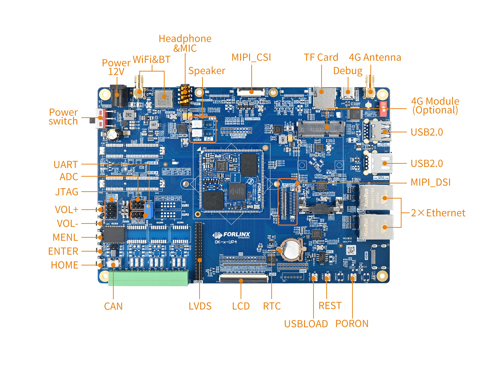
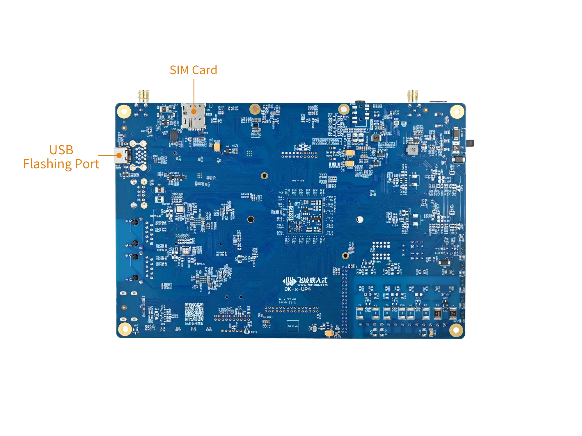
▊ Carrier Board
|
|
| i.MX9352-UP4 Development Board Function Parameters | ||
|---|---|---|
| Function | Quantity | Parameter |
| WiFi & Bluetooth | 1 | Single antenna 2.4G & 5GHz Wi-Fi Dual-band 1X1 802.11ac + Bluetooth 4.2 |
| Audio | 1 |
Dual - channel speaker interface, class - D, 1.3W; Stereo headphone output, 32Ohm load; Headphone recording |
| MIPI-CSI | 1 | Led out from the FPC socket, 2lane |
| TF Card | 1 | Data rate up to SDR104; |
| 4G | 1 | Supports 4G modules with a miniPCIE interface, integrating USB2.0 communication signals. |
| UART Debug | 1 | Integrated into a single Type-C port, enabling connection to a PC for debugging. |
| USB2.0 | 2 | 1 x USB-D native USB2.0 and 1 x USB-HUB are led out |
| Ethernet | 2 | 2 x Gigabit ports led out via a standard RJ45 socket |
| MIPI-DSI | 1 |
4-lane MIPI-DSI Screen, support capacitive touch and backlight adjustment Single lane maximum resolution 1920 × 1080 @ 60Hz |
| RTC | 1 | On-board CR1220 battery, keep going when power is off |
| RGB | 1 | RGB888 interface, supporting capacitive touch and resistive touch, and allowing backlight brightness adjustment. The maximum resolution is 1280×800. |
| LVDS | 1 | 4-lane LVDS, supporting capacitive touch screen and backlight brightness adjustment, up to 1280×800@60Hz |
| CAN | 1 | Supports CAN2.0, electrical quarantine |
| ADC | 3 | Led out from the pin header and can be connected to the on-board sliding rheostat |
| UART | 1 | 5 x UART, led out through pin headers. |
| BOOT | 1 | BOOT mode selection configuration |
| JTAG | 1 | JTAG, led out through pin |
| KEY ADC | 5 | 5 keys are led out via 1 x LRADC |
▊ Accessories
Please click here to get more information about the supported modules and accessories.
▊ Documentation
Reference Manuals
Hardware Related
Product Datasheet
User Guide
Carrier Board Schematic
Carrier Board PCB
SoM Pinmux
Software & BSP
OS Image
Testing Demo
Source Code
Manual
Request a Quote
Fill out the form below for volume pricing or technical specifications. We'll get back to you within 24 hours.
▊ Ordering Information
1. Online Channels: We have an online store on Alibaba and DigiKey. Please contact us for details.
2. Direct Inquiry: For bulk orders, please email our sales team at [email protected].
3. Payment Method: Standard terms: 100% T/T (Telegraphic Transfer) in advance.
1. Dispatch Method: Orders are shipped via international express upon receipt of payment.
2. Lead Time: 5 working days for samples; 6 weeks for bulk orders.
3. Shipping Policy: Shipping and handling fees are the responsibility of the purchaser.
▊ Forlinx Recommended Products
Architecture: Octa-core ARM Cortex-A55 (4+4 cluster)
Frequency: CPU 1.8GHz/1.4GHz | RISC-V 200MHz | DSP 600MHz
RAM: 2GB/4GB LPDDR4
ROM: 16GB / 32GB eMMC
Architecture: 4x [email protected]+RISC-V@600MHz
Frequency: 1.6GHZ
RAM: 1GB/2GB/4GB LPDDR4
ROM: 8GB/16GB/32GB eMMC
Architecture: Cortex-A55
Frequency: 1.8GHz,2.0GHz
RAM: 1GB / 2GB / 4GB / 8GB LPDDR4X
ROM: 8GB / 16GB / 32GB / 64GB eMMC
Architecture: 4×Cortex-A53
Frequency: [email protected]
RAM: 1GB/2GB LPDDR4
ROM: 8GB/16GB eMMC