


OK1126Bx-C Single Board Computer
CPU: Rockchip RV1126B/RV1126BJ
Architecture: 4x [email protected]
Frequency: 1.3GHz,1.6GHZ
RAM: 1GB/2GB/4GB LPDDR4
ROM: 8/16/32/64GB eMMC
System: Linux 6.1
Rockchip RV1126B / RV1126BJ Single Board Computer | 3 TOPS Edge AI SBC
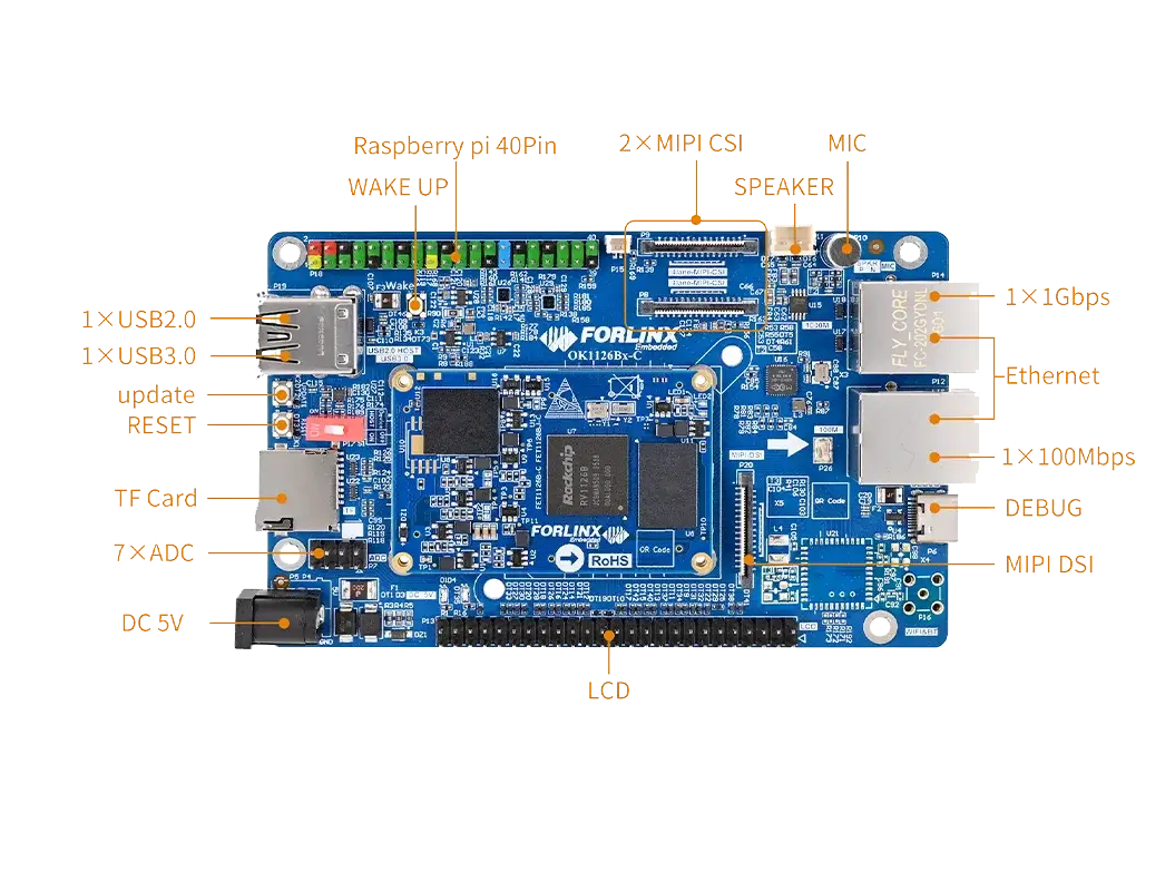
The OK1126B-C/OK1126BJ-C development board features a compact 120mm × 75mm footprint while offering extensive connectivity, including an Ethernet port, dual MIPI CSI, a single MIPI DSI, and a 40-pin Raspberry Pi-compatible GPIO header (supporting UART, SPI, I2C, and other buses). This enables the flexible expansion of various peripherals and sensor modules, making it ideal for embedded vision, edge computing, AIoT, and AI inference applications.
FET1126BJ-C SoM
3TOPS NPU | Edge AI | AOA+AOV Support | 10-15 Year Longevity
Functional Diagram
Robust Vision Engine for Multi-Stream Analysis
Compared to the RV1126, it offers three major enhancements: boosted CPU and NPU performance, plus an upgraded OS. Enjoy a more powerful, intelligent, and seamless device AI journey.
FET1126B‑C / FET1126BJ‑C SoM
Designed in an ultra-compact footprint (56 × 36 mm), the FET1126B-C/FET1126BJ-C SoM uses three 80-pin board-to-board connectors (240 pins total; 0.5 mm pitch, 2.0 mm mated height) for reliable assembly.
All RV1126B/RV1126BJ I/Os—camera, display, audio, Ethernet, and serial buses—are fully accessible, enabling flexible carrier-board expansion and custom development.
▊ Hardware Features
| FET1126Bx-C SoM Parameters | ||
|---|---|---|
| Processor | Rockchip RV1126B | Rockchip RV1126BJ |
| CPU: 4×Cortex-A53, up to 1.6GHz | CPU: 4×Cortex-A53, up to 1.3GHz | |
| NPU: 3 TOPS@INT8 | ||
| GPU: No 3D GPU; supports 2D RGA only | ||
|
ISP: VICAP input: RX raw8/raw10/raw12/raw14/raw16 Maximum input: 12M@20fps Minimum input: 264x264 |
||
|
AI ISP: Maximum input: 8M@30fps Maximum Resolution: 4096 x 4096 |
||
|
VPU Video Decoder: - Supports H.264 and H.265 hardware decoding - H.265 HEVC/MVC Main Profile [email protected] up to 3840x2160@30fps - H.264 AVC/MVC Main Profile yuv400/yuv420/[email protected] up to 3840x2160@30fps VPU Video Encoder: - Supports HEVC, H.264 and JPEG hardware encoding - Supports parallel encoding (HEVC+JPEG or H.264+JPEG) - Supports up to 12M@30fps JPEG decoder: - Supported image resolutions: 48x48 to 65520x65520 - Supports YUV400/YUV420/YUV422/YUV440/YUV411/YUV444 |
||
| RAM | 1GB/2GB/4GB LPDDR4 | |
| ROM | 64GB eMMC | 8GB/16GB/32GB/64GB eMMC |
| Operating Temperature | -20℃ ~ +85℃ | -40℃ ~ +85℃ |
| Operating Voltage | DC 5V | |
| OS | Linux 6.1.141 | |
| Flashing | USB OTG, TF | |
| Connection | Ultra-thin board-to-board connector (3*80pin, 0.5 mm pitch, total height 2.0 mm) | |
| FET1126Bx-C SoM Function Parameters | ||
|---|---|---|
| Function | Quantity | Parameter |
| Display | 1 |
Supports 1 x display output, with a maximum resolution of 1920*1080@60fps Supports various display interfaces: - RGB: 24bit - MIPI-DSI: 4lane, 1.5Gbps/lane - BT.656/BT.1120 |
| MIPI CSI | ≤2 |
Supports 2 x 4lane, 2.5Gbps/lane - Supports two MIPI CSI/LVDS/SubLVDS DPHYs - Each MIPI DPHY V1.2, 4lane, 2.5Gbps/lane - Each interface can be configured as a 2x2 data channel port - Virtual channels are supported |
| DVP | 1 |
Supports 8/10/12/14/16-bit, with an I/O frequency of up to 150 MHz Supports BT.601/ BT.656 and BT.1120 Input |
| Ethernet | 1 | 1 x MAC, which can be used for either one RGMII interface or one 100 Mbit/s interface (the CPU has one integrated 100 Mbit/s PHY) |
| USB | 2 |
1 x USB 2.0 Host 1 x USB 2.0/3.0 DRD |
| UART | ≤8 | The maximum supported baud rate is 4 Mbps; UART1–UART7 support automatic flow control. |
| CAN | ≤2 | Supports CAN2.0/B |
| SDIO 3.0 | ≤2 | 1 x TF card slot, supporting high-speed cards; 1 x SDIO interface, 3.3V logic level |
| DSMC | ≤1 |
1 x host interface, which can be used to connect to an FPGA Supports 4 chip-select signals and 8-wire or 16-wire serial transmission modes |
| FSPI | ≤1 | Supports boot-up; 1/2/4-bit modes |
| SPI | ≤2 | Configurable master-slave mode |
| I2C | ≤5 | Supports 7bits and 10bits address modes up to 1 Mbit/s |
| PWM | ≤27 | Supports up to 27 channels of PWM. |
| ADC | ≤24 | 24 single-ended inputs, 13bit, 2 MSPS |
| SAI | ≤3 | Configurable master-slave mode |
| Audio ADC | ≤2 | 2 x differential MIC inputs, 2 x Audio DSM differential outputs |
| GPIO | ≤118 | The total quantity excluding the internal use of the SoM |
Note*: Note: The parameters in the table are based on hardware design or theoretical CPU values.
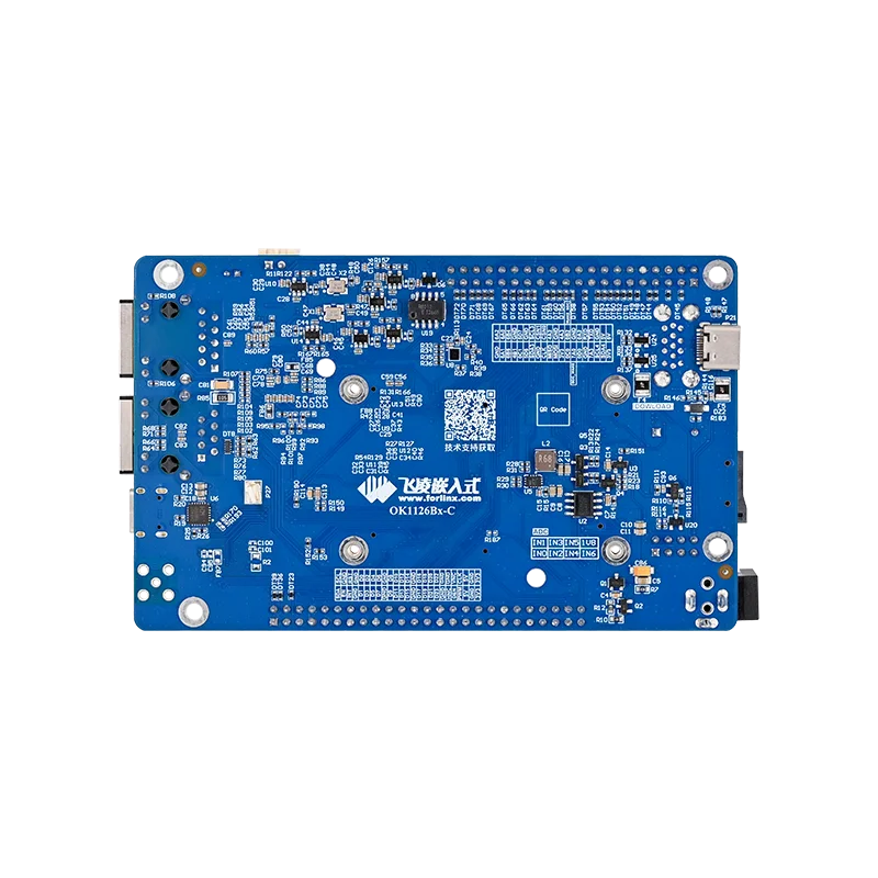
▊ Carrier Board
|
|
| OK1126Bx-C Development Board Function Parameters | ||
|---|---|---|
| Function | Quantity | Parameter |
| TF Card | 1 | Data rate up to SDR104; |
| KEY | 3 | CPU Reset, Boot Options and Wake-up Button |
| UART Debug | 1 | Integrated into a single Type-C port, enabling connection to a PC for debugging. |
| USB2.0 | 2 | 1 x USB_HOST port is connected via a USB socket; 1 x USB_OTG port is connected via a Type-C connector for use with OTG programming or, when combined with USB 3.0, via a USB 3.0 socket. |
| USB3.0 | 1 | The USB 3.0 host is connected to the USB 3.0 socket. |
| WiFi Bluetooth (1) | 1 |
Single antenna 2.4G&5GHz Wi-Fi Dual-band 1X1 802.11ac + Bluetooth 4.2 |
| SPI | 1 | SPI1 is routed out via the Raspberry Pi’s 40PIN header |
| RTC | 1 | Powered by an external CR2032 button cell; data retention time when power is off |
| Ethernet | 1 | Featuring a standard RJ45 socket, with either a 100 Mbps port or a 1 Gbps port, the RV1126B is equipped with a single GMAC controller. This allows it to provide RMII/RGMII interfaces for connecting external 100 Mbps or one Gbps Ethernet PHY chips, or to switch to the built-in 100 Mbps FEPHY. Only one of these options can be selected at a time; they cannot be used simultaneously. |
| UART | 1 | UART5 is routed out via the Raspberry Pi’s 40PIN header |
| I2C | 2 | I2C3 and I2C4 are connected via the Raspberry Pi’s 40PIN header |
| SPEAKER | 1 | Through the power amplifier chip, it can be connected to an external 4Ω–3.3W speaker. |
| MIC | 2 | One channel is connected to the onboard electret microphone, and the other channel is not externally accessible. |
| ADC | 7 | 7 x ADC are routed out via pin headers. |
| MIPI-CSI | 2 | Routed out via an FPC connector, 4 lanes + 4 lanes. |
| LCD | 1 | Routed out via pin headers, supports capacitive touch screens. |
| MIPI_DSI | 1 | 4-lane MIPI-DSI, supports capacitive touch screens |
Note: The parameters in the table are based on hardware design or theoretical CPU values.WiFi/Bluetooth is currently not supported in this version; the carrier board circuit can be referenced.
▊ Accessories
Please click here to get more information about the supported modules and accessories.
▊ Documentation
Reference Manuals
Hardware Related
Product Datasheet
User Guide
Carrier Board Schematic
Carrier Board PCB
SoM Pinmux
Software & BSP
OS Image
Testing Demo
Source Code
Manual
Request a Quote
Fill out the form below for volume pricing or technical specifications. We'll get back to you within 24 hours.
▊ Ordering Information
1. Online Channels: We have an online store on Alibaba and DigiKey. Please contact us for details.
2. Direct Inquiry: For bulk orders, please email our sales team at [email protected].
3. Payment Method: Standard terms: 100% T/T (Telegraphic Transfer) in advance.
1. Dispatch Method: Orders are shipped via international express upon receipt of payment.
2. Lead Time: 5 working days for samples; 6 weeks for bulk orders.
3. Shipping Policy: Shipping and handling fees are the responsibility of the purchaser.
▊ Forlinx Recommended Products
Architecture: 4x [email protected]
Frequency: 1.6GHZ
RAM: 2GB/4GB
ROM: 16GB/64GB eMMC
Architecture: 2x [email protected] + 6x [email protected]
Frequency: [email protected],[email protected]
RAM: 2GB / 4GB / 8GB LPDDR5
ROM: 64GB eMMC
Architecture: 4x [email protected]
Frequency: 1.3GHz,1.6GHZ
RAM: 1GB/2GB/4GB LPDDR4
ROM: 8/16/32/64GB eMMC