


OK3576J-UP5 Single Board Computer
CPU: Rockchip RK3576
Architecture: 4x Cortex-A72 + 4x Cortex-A53
Frequency: [email protected][email protected]
RAM: 8GB LPDDR4,2GB/4GB LPDDR4
ROM: 16GB eMMC,32GB/64GB eMMC
System: Android14,ForlinxDesktop 24.04,Linux 6.1
OK3576J-UP5 Development Board | Rockchip RK3576 Industrial Evaluation Kit
The OK3576J-UP5 Development Board / Single Board Computer combines the industrial-grade FET3576J-UP5 SoM with a full-featured carrier board to deliver a production-ready evaluation platform. Built around the Rockchip RK3576 processor, it integrates quad-channel MIPI CSI, 8K HDMI output, dual Gigabit Ethernet, PCIe 2.1, and 5G expansion, eliminating low-level hardware design friction and streamlining rapid prototyping for smart vision, AIoT, and industrial control .
FET3576-UP5 / FET3576J-UP5 SoM
FET3576J-UP5 SoM is equipped with the Rockchip RK3576 processor (4×A72 + 4×A53),
integrating a 6 TOPS NPU that delivers both high performance and low power consumption, providing strong support for AIoT and industrial applications.
The product has undergone rigorous testing in harsh industrial environments, ensuring exceptional stability, and offers long-term supply support of 10–15 years.
What is UP5 Packaging?
UP5 is a System on Module (SoM) packaging standard defined by Forlinx Embedded. "UP" stands for "Universal Package," while "5" indicates the ultra-compact board size of 50mm × 50mm.
This series employs a Land Grid Array (LGA) interface with a total of 624 pins. The LGA solder ball pitch measures 1.25mm, and each solder ball diameter is 0.8mm.
SoM UP5 Advantages
The UP5 series establishes an open standard for SoM hardware compatibility and interchangeability. By defining unified physical dimensions, soldering packages, and pin layouts, it minimizes R&D difficulty and risk.
Hardware Design Reusability: A single carrier board design can adapt to multiple SoM platforms across various performance tiers.
Supply Chain Flexibility: SoMs can utilize chips from multiple silicon vendors, effectively mitigating component supply risks.
Compact Size: The UP5 series balances size, thermal performance, and cost while maintaining pin standardization.
Wide Range of UP5 SoM Options
Forlinx Embedded currently offers UP5 products based on Rockchip RK3576 and RK3576 processors,
with additional UP5 family products continuously launching to support multi-tier platform scaling.
Boost Your AI Apps with 6TOPS Computing Power NPU
6TOPS super-computing power NPU, support INT4/INT8/INT16/FP16/BF16/TF32 operation, support dual-core work together or work independently,
support multi-task, multi-scenario parallel, support deep learning frameworks: TensorFlow, Caffe, Tflite, Pytorch, Onnx NN, Android NN, etc.
New Parallel Bus Interface for FlexBus
FlexBus: Flexible parallel bus interface, capable of emulating irregular or standard protocols, supporting 2/4/8/16-bit data parallel transmission, with a clock speed of up to 100MHz.
It also features a rich array of bus transfer interfaces including DSMC, CAN-FD, PCIe 2.1, SATA 3.0, USB 3.2, SAI, I2C, I3C, UART, and more.
Firewall Enables True Isolation of Hardware Resource
RK3576 supports Firewall functionality, used to manage access permissions from the main device to peripheral devices and memory areas, achieving true hardware resource isolation.
This feature not only enhances system stability and security but also provides robust support for a variety of application scenarios.
Multiple Operating Systems Support
Forlinx Embedded customizes Android, Linux, and Forlinx Desktop operating systems for RK3576 development platforms.
Comprehensive multi-layer industrial testing guarantees 24/7 stable operation, accommodating diverse application workflows.
Wide Range of Application Scenarios
Supercharge your innovations with the versatile FET3576-C SoM! From industrial, AIoT, edge computing, smart mobile terminals, and various other digital multimedia-related fields.
With Forlinx's robust technical support services, accelerate your product's time-to-market and seize the lead in your industry.
Mechanical Dimensions
Equipped with the Rockchip RK3576/RK3576J industrial processor, the module adopts an LCC+LGA package (624 pins) that routes out all functional signals within a compact 50mm × 50mm size.
It enables flexible heat dissipation design and reduces structural enclosure volume for space-constrained installations.
Forlinx UP5 Standard
What is UP5? A Compatible and Compact Package
▊ Hardware Features
| Hardware Parameters of FET3576-UP5 | ||
|---|---|---|
| Processor | Rockchip RK3576 / RK3576J | |
| ARM: 4×Cortex-A72 + 4×Cortex-A53 | ||
| NPU | 6TOPS INT8, supports INT4/INT8/INT16/FP16/BF16/TF32 | |
| GPU | ARM Mali-G52 MC3, supports OpenGL ES 1.1/2.0/3.2, OpenCL 2.0, Vulkan 1.1 | |
| VPU |
Hardware Decoding: • H.264, H.265, VP9, AV1, AVS2, 8K@30fps or 4K@120fps |
|
|
Hardware Encoding: • H.264, H265, 4K@60fps |
||
| RAM | 2GB/4GB/8GB LPDDR4 | |
| ROM | 16GB/32GB/64GB eMMC | |
| Working Voltage | DC 5V-13V | |
| Operating Temperature |
FET3576-UP5 SoM: 0℃~+70℃ FET3576J-UP5 SoM: -40℃~+85℃ |
|
| Net Weight | 14.4g | |
| Connection | LGA (624 pins; the ball pitch of the LGA is 1.25 mm, and the diameter of a single ball is 0.8 mm) | |
| OS | Linux 84, Forlinx Desktop 24.04 (based on Ubuntu 24.04 file system), Android 14 | |
| Flashing method |
|
|
| SoM Function Parameters of FET3576-UP5 | ||||
|---|---|---|---|---|
| Function | Maximum Number | Parameter | Number of interfaces defined by UP5 | Parameter |
| MIPI CSI | 5 |
Supports 5 CSI-2 Interfaces: Four of these interfaces each have 2 D-PHY v1.2 data lanes, with 2.5 Gbps per lane; These four interfaces can be combined into two interfaces, each with 4 data lanes; The fifth interface supports either 4 D-PHY data lanes or 3 C-PHY trios; D-PHY v2.0 lane speed: 4.5 Gbps; C-PHY v1.1 trio speed: 2.4 Gsps. |
4 |
Supports 4 CSI-2 Interfaces Three of these interfaces each have 2 D-PHY v1.2 data lanes, with 2.5 Gbps per lane; The fourth interface supports either 4 D-PHY data lanes or 3 C- PHY trios; D-PHY v2.0 lane speed: 4.5 Gbps; C-PHY v1.1 trio speed: 2.4 Gsps. |
| DVP | 1 | Standard DVP interface (8/10/12/16-bit, up to 150 Mhz); Supports BT.601, BT.656, and BT.1120 VI interfaces | \ | |
| HDMI/eDP TX | 1 |
Supports 1 HDMI / eDP TX combined interface HDMI Interface HDMI v2.1 Supports up to 4K@120 Hz Data formats: RGB/YUV444/YUV422/YUV420 8/10-bit Supports CEC and ARC HDCP v2.3 and HDCP v1.4 eDP Interface eDP v1.3 Main link includes 4 physical lanes Supports up to 4K@60 Hz HDCP v1.3 |
1 |
Supports 1 HDMI_TX interface. HDMI Interface HDMI v2.1 Supports up to 4K@120 Hz Data formats: RGB/YUV444/YUV422/YUV420 8/10-bit Supports CEC and ARC HDCP v2.3 and HDCP v1.4 |
| DP&USB 3.2Gen1 OTG | 1 |
Supports 1 USB / DP combined interface. USB Interface USB 3.2 Gen1x1 Dual-Role Device (DRD) DisplayPort TX Interface DisplayPort v1.4 Supports 1/2/4 lanes with lane speeds of 1.62, 2.7, 5.4, and 8.1 Gbps Supports up to 4K@120 Hz Data formats: RGB/YUV444/YUV422/YUV420 8/10-bit Supports Multi-Stream Transport (MST) with 3 displays Supports DP Altmode on USB Type-C Supports HDCP v2.3 and HDCP v1.3 |
\ |
Supports 1 USB / DP combined interface. USB Interface USB 3.2 Gen1x1 Dual-Role Device (DRD) DisplayPort TX Interface DisplayPort v1.4 Supports 1/2/4 lanes with lane speeds of 1.62, 2.7, 5.4, and 8.1 Gbps Supports up to 4K@120 Hz Data formats: RGB/YUV444/YUV422/YUV420 8/10-bit Supports Multi-Stream Transport (MST) with 3 displays Supports DP Altmode on USB Type-C Supports HDCP v2.3 and HDCP v1.3 |
| MIPI DSI | 1 |
Supports 1 MIPI DSI-2 TX interface. D-PHY v2.0 or C-PHY v1.1 4 data lanes on D-PHY 3 data trios on C-PHY Supports up to 2560 × 1600@60 Hz Data format: RGB (up to 10-bit) |
1 |
Supports 1 MIPI DSI-2 TX interface. D-PHY v2.0 or C-PHY v1.1 4 data lanes on D-PHY 3 data trios on C-PHY Supports up to 2560 × 1600@60 Hz Data format: RGB (up to 10-bit) |
| Parallel | 1 |
Supports 1 parallel output interface. Supports RGB/BT.656/BT1120 Supports up to 1920 × 1080@60 Hz Data format: RGB (up to 10-bit) |
\ | |
| EBC | 1 |
Supports 1 EBC output interface. Supports E-ink EPD (Electronic Paper Display) Supports 2560 × 1920 hardware decoding Data bus width: 16-bit Supports up to 32-level gray scale Supports Direct mode, LUT mode, 3-window mode Supports window display mode |
\ | |
| SAI | ≤5 |
Supports 5 SAI interfaces. SAI 0/1 supports 4 TX lanes and 4 RX lanes. SAI 2/3/4 supports 1 TX lane and 1 RX lane. Supports I2S/TDM/PCM mode Maximum sample rate: 192 kHz Audio resolution: 16 to 32 bits |
1 |
Supports 1 SAI interface. SAI 2 supports 1 TX lane and 1 RX lane. Supports I2S/TDM/PCM mode Maximum sample rate: 192 kHz Audio resolution: 16 to 32 bits |
| SPDIF TX | ≤2 | · Supports 2 x SPDIF TX ports; | \ | |
| SPDIF RX | ≤2 | · Supports 2 x SPDIF RX ports; | \ | |
| PDM | ≤2 |
Up to 8 channels, audio resolution: 16-bit to 24-bit, sample rate up to 192 kHz; Supports PDM master receive mode |
\ | |
| Ethernet | ≤2 |
2 × GMAC with RGMII / RMII interfaces; Supports Data rates: 10/100/1000 Mbps |
2 |
2 × GMAC with RGMII / RMII interfaces; Supports Data rates: 10/100/1000 Mbps |
| Combo high speed interface | 2 |
Supports 1 x PCIe2.1/SATA3.1 interface with one data lane; Supports 1 x PCIe2.1/SATA3.1/USB3.2 Gen1x1 interface with one data lane |
2 | Supports 1 x PCIe2.1/SATA3.1 interface with one data lane |
| USB 2.0 OTG | 2 | · 2 x USB2.0 OTG | \ | |
| SDIO | ≤2 | ·SDIO v3.0, 4-bit data bus widths | 2 | ·SDIO v3.0, 4-bit data bus widths |
| SPI | ≤5 | Supports two chip-select in each interface; Supports serial-master and serial-slave mode | 2 | Supports two chip-select in each interface; Supports serial-master and serial-slave mode |
| I2C | ≤9 |
Supports 7-bit and 10-bit address modes; Data transmission rate of 100K bits/s in standard mode and 400k bits/s in fast mode. |
4 |
Supports 7-bit and 10-bit address modes; Data transmission rate of 100K bits/s in standard mode and 400k bits/s in fast mode. |
| I3C | ≤2 | ·Supports 2 x I3C master ports | \ | |
| UART | ≤12 |
Built-in 2 × 64-bit FIFO (separate TX/RX) Supports 5-, 6-, 7-, 8-bit serial data transmission Baud rate up to 4 Mbps 12 × UART all support auto-flow-control (AFC) mode 12 × UART all support RS-485 mode |
4 | Both UART support automatic flow control mode and RS485 mode. |
| CAN | ≤2 |
Compliant with CAN & CAN FD specifications; Supports standard & extended frame transmission 8192-bit receive FIFO; |
2 |
Compliant with CAN & CAN FD specifications; Supports standard & extended frame transmission 8192-bit receive FIFO; |
| DSMC | ≤1 |
·Supports up to select 4 chips ·Supports 8-wire and 16- wire serial transfer mode ·Supports configurable serial address width:16 bits or 32 bits |
\ | |
| FlexBus | ≤1 |
·Supports built-in DMA and ping- pong operation for allocating two address ·Supports transmission and receiving mode ·Supports single mode and continuous mode |
\ | |
| PWM | ≤16 | Supports up to 16 on-chip PWM with interrupt-based operation and capture mode; | 2 | Supports up to 2 on-chip PWM with interrupt-based operation and capture mode; |
| ADC | ≤8 | · Supports 8 x 12bit single-ended input SAR-ADC with sampling rate up to 1MS/s; | 4 | · Supports 4 x 12bit single-ended input SAR-ADC with sampling rate up to 1MS/s; |
| GPIO | n |
All GPIOs can be used to generate interrupts; Supports level-triggered and edge- triggered interrupts; Supports configuration of level- triggered polarity; Supports rising-edge, falling-edge and dual-edge interrupts; Supports configuration of pull- up/pull-down (weak pull-up and weak pull-down); Supports configuration of drive capability Configurable drive strength. |
16 |
All GPIOs can be used to generate interrupts; Supports level-triggered and edge- triggered interrupts; Supports configuration of level- triggered polarity; Supports rising-edge, falling-edge and dual-edge interrupts; Supports configuration of pull- up/pull-down (weak pull-up and weak pull-down); Supports configuration of drive capability Configurable drive strength. |
Note*: The maximum number of parameters in the table is the theoretical value of hardware design or CPU; The number of interface resources defined by UP5 in the table is the maximum number supported by the UP5 universal package.
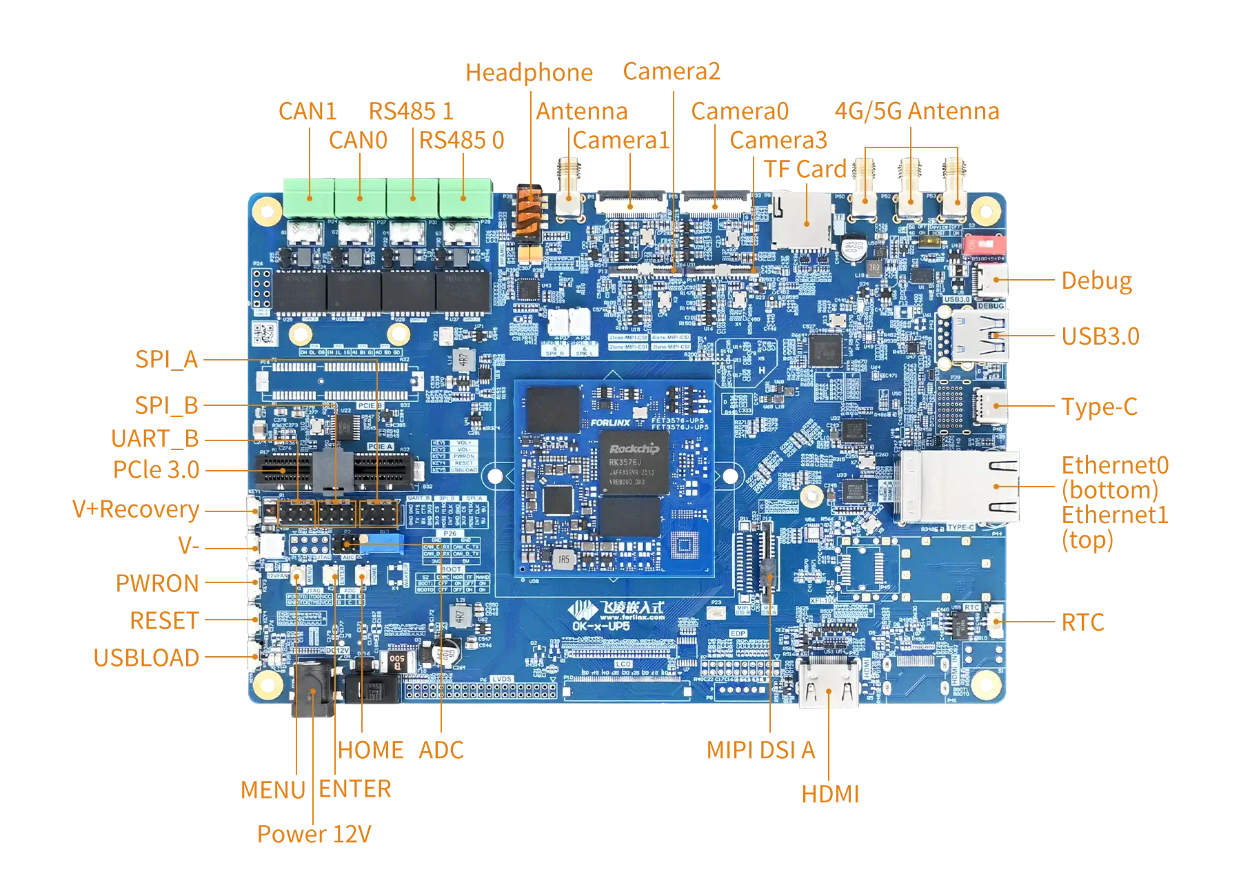
▊ Carrier Board
|
|
| Development Board Function Parameters | ||
|---|---|---|
| Function | Quantity | Parameter |
| MIPI CSI | 4 | 1 x MIPI DPHY V2.0 4-lane interface, supporting up to 4.5 Gbps per lane; connected via a 26-pin FPC socket, with the OV13850 camera mounted by default; 3 x MIPI DPHY V1.2 2-lane interfaces, supporting up to 2.5 Gbps per lane; brought out via three 26-pin FPC sockets; pre-mounted with an OV5645 camera by default; |
| MIPI DSI | 1 | Each MIPI interface supports 4 lanes of output, with a maximum resolution of 2560 x 1600@60Hz; Compatible with Forlinx 7-inch MIPI display, with a resolution of 1024 x 600@30fps; |
| HDMI TX | 1 | Led out via a standard HDMI connector; supports up to 7680x4320@60Hz. |
| USB3.2 Gen1 | 1 | Routed through a Type-C connector; |
| USB3.0 Host | 1 | Routed through a Type-A USB connector; |
| PCIe2.1 | 1 | Led out x 4 slot; · Supports 5Gbps speed; |
| Ethernet | 2 | Connected via a single dual-layer RJ45 socket; · Supports data transfer rates of 10/100/1000 Mbps; |
| TF Card | 1 | TF card is available, rate up to 150MHz,support SDR104 mode; |
| Audio | 1 | On-board codec chip, supporting functions such as headphone output, microphone input and speaker output; |
| RS485 | 2 | 2 x RS485 CAN bus routed out through RS485 transceiver; |
| CAN | 2 | Connect one CAN bus via the CANFD transceiver; |
| UART | 1 | Led out via 2.54 mm pitch;Up to 4Mbps baud rate; |
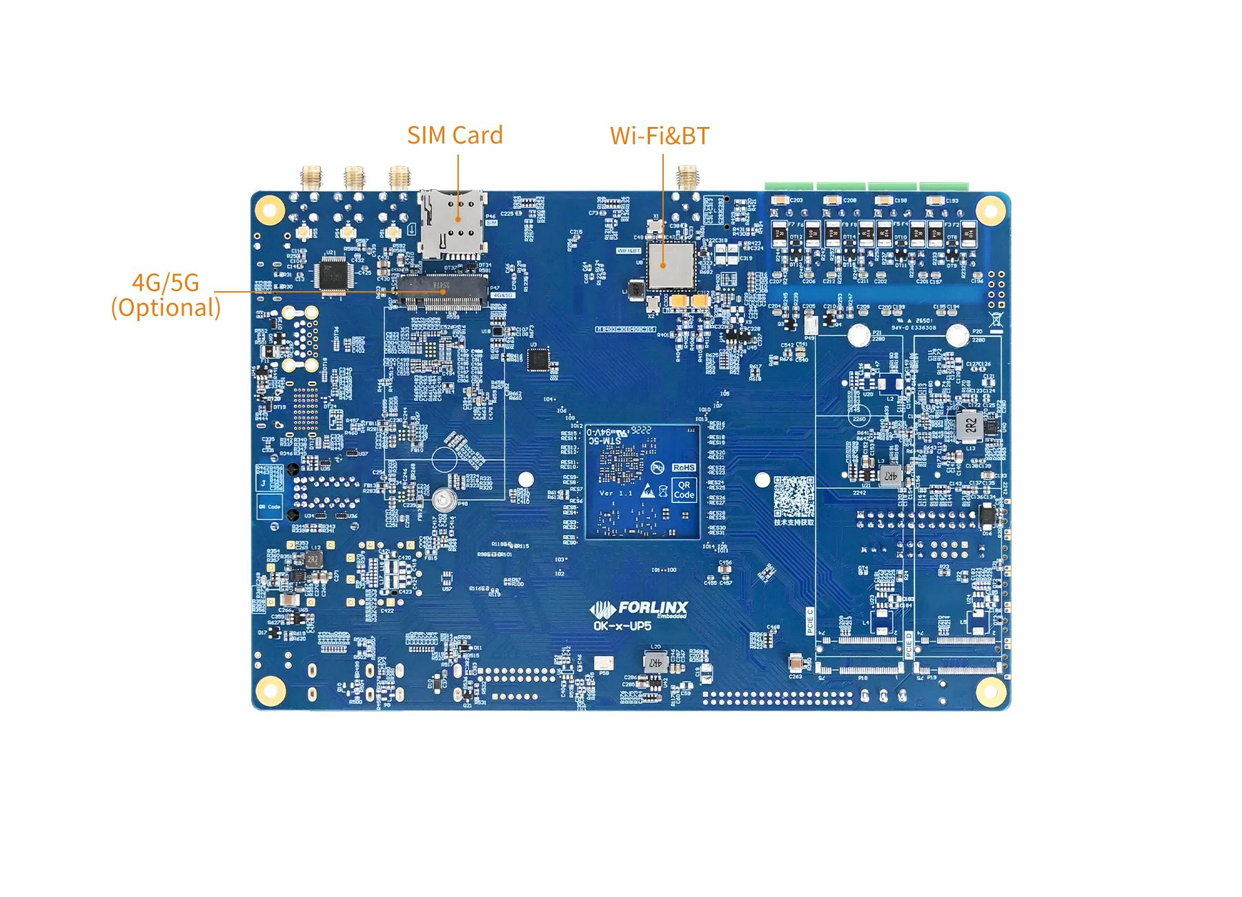
| 4G/5G | 1 | Supports M.2 packaged 4G/5G modules; |
| WIFI&BT | 1 | On-board Wi-Fi and Bluetooth module; an external Wi-Fi antenna must be connected |
| ADC | 3 | Led out via a PH2.0 socket; · 12-bit resolution and a sampling rate of up to 1 MS/s; |
| RTC | 1 | Onboard RTC chip and battery socket; |
| SPI | 2 | Routed through a 2.54mm pitch connector; |
| FAN | 1 | On-board fan connector; |
Note*: The parameters in the table are the theoretical values of hardware design or CPU.
▊ Accessories
Please click here to get more information about the supported modules and accessories.
▊ Documentation
Reference Manuals
Hardware Related
Product Datasheet
User Guide
Carrier Board Schematic
Carrier Board PCB
SoM Pinmux
Software & BSP
OS Image
Testing Demo
Source Code
Manual
Request a Quote
Fill out the form below for volume pricing or technical specifications. We'll get back to you within 24 hours.
▊ Ordering Information
1. Online Channels: We have an online store on Alibaba and DigiKey. Please contact us for details.
2. Direct Inquiry: For bulk orders, please email our sales team at [email protected].
3. Payment Method: Standard terms: 100% T/T (Telegraphic Transfer) in advance.
1. Dispatch Method: Orders are shipped via international express upon receipt of payment.
2. Lead Time: 5 working days for samples; 6 weeks for bulk orders.
3. Shipping Policy: Shipping and handling fees are the responsibility of the purchaser.
▊ Forlinx Recommended Products
Architecture: 4x Cortex-A72 + 4x Cortex-A53
Frequency: [email protected][email protected]
RAM: 8GB LPDDR4,2GB/4GB LPDDR4
ROM: 16GB eMMC,32GB/64GB eMMC
Architecture: 4x Cortex-A76+4x Cortex-A55
Frequency: [email protected]/1.6GHz, [email protected]/1.3GHz
RAM: 4GB/8GB/16GB/32GB LPDDR4
ROM: 32GB/64GB/128GB eMMC