


OK3576J-UP5 Single Board Computer
CPU: Rockchip RK3576
Architecture: 4x Cortex-A72 + 4x Cortex-A53
Frequency: [email protected][email protected]
RAM: 8GB LPDDR4,2GB/4GB LPDDR4
ROM: 16GB eMMC,32GB/64GB eMMC
System: Android14,ForlinxDesktop 24.04,Linux 6.1
OK3576J-UP5 Development Board | Rockchip RK3576 Industrial Evaluation Kit
The OK3576J-UP5 Development Board / Single Board Computer combines the industrial-grade FET3576J-UP5 SoM with a full-featured carrier board to deliver a production-ready evaluation platform. Built around the Rockchip RK3576 processor, it integrates quad-channel MIPI CSI, 8K HDMI output, dual Gigabit Ethernet, PCIe 2.1, and 5G expansion, eliminating low-level hardware design friction and streamlining rapid prototyping for smart vision, AIoT, and industrial control.
▊ Hardware Features
| Hardware Parameters of FET3576-UP5 | ||
|---|---|---|
| Processor | Rockchip RK3576 / RK3576J | |
| ARM: 4×Cortex-A72 + 4×Cortex-A53 | ||
| NPU | 6TOPS INT8, supports INT4/INT8/INT16/FP16/BF16/TF32 | |
| GPU | ARM Mali-G52 MC3, supports OpenGL ES 1.1/2.0/3.2, OpenCL 2.0, Vulkan 1.1 | |
| VPU |
Hardware Decoding: • H.264, H.265, VP9, AV1, AVS2, 8K@30fps or 4K@120fps |
|
|
Hardware Encoding: • H.264, H265, 4K@60fps |
||
| RAM | 2GB/4GB/8GB LPDDR4 | |
| ROM | 16GB/32GB/64GB eMMC | |
| Working Voltage | DC 5V-13V | |
| Operating Temperature |
FET3576-UP5 SoM: 0℃~+70℃ FET3576J-UP5 SoM: -40℃~+85℃ |
|
| Net Weight | 14.4g | |
| Connection | LGA (624 pins; the ball pitch of the LGA is 1.25 mm, and the diameter of a single ball is 0.8 mm) | |
| OS | Linux 84, Forlinx Desktop 24.04 (based on Ubuntu 24.04 file system), Android 14 | |
| Flashing method |
|
|
| SoM Function Parameters of FET3576-UP5 | ||||
|---|---|---|---|---|
| Function | Maximum Number | Parameter | Number of interfaces defined by UP5 | Parameter |
| MIPI CSI | 5 |
Supports 5 CSI-2 Interfaces: Four of these interfaces each have 2 D-PHY v1.2 data lanes, with 2.5 Gbps per lane; These four interfaces can be combined into two interfaces, each with 4 data lanes; The fifth interface supports either 4 D-PHY data lanes or 3 C-PHY trios; D-PHY v2.0 lane speed: 4.5 Gbps; C-PHY v1.1 trio speed: 2.4 Gsps. |
4 |
Supports 4 CSI-2 Interfaces Three of these interfaces each have 2 D-PHY v1.2 data lanes, with 2.5 Gbps per lane; The fourth interface supports either 4 D-PHY data lanes or 3 C- PHY trios; D-PHY v2.0 lane speed: 4.5 Gbps; C-PHY v1.1 trio speed: 2.4 Gsps. |
| DVP | 1 | Standard DVP interface (8/10/12/16-bit, up to 150 Mhz); Supports BT.601, BT.656, and BT.1120 VI interfaces | \ | |
| HDMI/eDP TX | 1 |
Supports 1 HDMI / eDP TX combined interface HDMI Interface HDMI v2.1 Supports up to 4K@120 Hz Data formats: RGB/YUV444/YUV422/YUV420 8/10-bit Supports CEC and ARC HDCP v2.3 and HDCP v1.4 eDP Interface eDP v1.3 Main link includes 4 physical lanes Supports up to 4K@60 Hz HDCP v1.3 |
1 |
Supports 1 HDMI_TX interface. HDMI Interface HDMI v2.1 Supports up to 4K@120 Hz Data formats: RGB/YUV444/YUV422/YUV420 8/10-bit Supports CEC and ARC HDCP v2.3 and HDCP v1.4 |
| DP&USB 3.2Gen1 OTG | 1 |
Supports 1 USB / DP combined interface. USB Interface USB 3.2 Gen1x1 Dual-Role Device (DRD) DisplayPort TX Interface DisplayPort v1.4 Supports 1/2/4 lanes with lane speeds of 1.62, 2.7, 5.4, and 8.1 Gbps Supports up to 4K@120 Hz Data formats: RGB/YUV444/YUV422/YUV420 8/10-bit Supports Multi-Stream Transport (MST) with 3 displays Supports DP Altmode on USB Type-C Supports HDCP v2.3 and HDCP v1.3 |
\ |
Supports 1 USB / DP combined interface. USB Interface USB 3.2 Gen1x1 Dual-Role Device (DRD) DisplayPort TX Interface DisplayPort v1.4 Supports 1/2/4 lanes with lane speeds of 1.62, 2.7, 5.4, and 8.1 Gbps Supports up to 4K@120 Hz Data formats: RGB/YUV444/YUV422/YUV420 8/10-bit Supports Multi-Stream Transport (MST) with 3 displays Supports DP Altmode on USB Type-C Supports HDCP v2.3 and HDCP v1.3 |
| MIPI DSI | 1 |
Supports 1 MIPI DSI-2 TX interface. D-PHY v2.0 or C-PHY v1.1 4 data lanes on D-PHY 3 data trios on C-PHY Supports up to 2560 × 1600@60 Hz Data format: RGB (up to 10-bit) |
1 |
Supports 1 MIPI DSI-2 TX interface. D-PHY v2.0 or C-PHY v1.1 4 data lanes on D-PHY 3 data trios on C-PHY Supports up to 2560 × 1600@60 Hz Data format: RGB (up to 10-bit) |
| Parallel | 1 |
Supports 1 parallel output interface. Supports RGB/BT.656/BT1120 Supports up to 1920 × 1080@60 Hz Data format: RGB (up to 10-bit) |
\ | |
| EBC | 1 |
Supports 1 EBC output interface. Supports E-ink EPD (Electronic Paper Display) Supports 2560 × 1920 hardware decoding Data bus width: 16-bit Supports up to 32-level gray scale Supports Direct mode, LUT mode, 3-window mode Supports window display mode |
\ | |
| SAI | ≤5 |
Supports 5 SAI interfaces. SAI 0/1 supports 4 TX lanes and 4 RX lanes. SAI 2/3/4 supports 1 TX lane and 1 RX lane. Supports I2S/TDM/PCM mode Maximum sample rate: 192 kHz Audio resolution: 16 to 32 bits |
1 |
Supports 1 SAI interface. SAI 2 supports 1 TX lane and 1 RX lane. Supports I2S/TDM/PCM mode Maximum sample rate: 192 kHz Audio resolution: 16 to 32 bits |
| SPDIF TX | ≤2 | · Supports 2 x SPDIF TX ports; | \ | |
| SPDIF RX | ≤2 | · Supports 2 x SPDIF RX ports; | \ | |
| PDM | ≤2 |
Up to 8 channels, audio resolution: 16-bit to 24-bit, sample rate up to 192 kHz; Supports PDM master receive mode |
\ | |
| Ethernet | ≤2 |
2 × GMAC with RGMII / RMII interfaces; Supports Data rates: 10/100/1000 Mbps |
2 |
2 × GMAC with RGMII / RMII interfaces; Supports Data rates: 10/100/1000 Mbps |
| Combo high speed interface | 2 |
Supports 1 x PCIe2.1/SATA3.1 interface with one data lane; Supports 1 x PCIe2.1/SATA3.1/USB3.2 Gen1x1 interface with one data lane |
2 | Supports 1 x PCIe2.1/SATA3.1 interface with one data lane |
| USB 2.0 OTG | 2 | · 2 x USB2.0 OTG | \ | |
| SDIO | ≤2 | ·SDIO v3.0, 4-bit data bus widths | 2 | ·SDIO v3.0, 4-bit data bus widths |
| SPI | ≤5 | Supports two chip-select in each interface; Supports serial-master and serial-slave mode | 2 | Supports two chip-select in each interface; Supports serial-master and serial-slave mode |
| I2C | ≤9 |
Supports 7-bit and 10-bit address modes; Data transmission rate of 100K bits/s in standard mode and 400k bits/s in fast mode. |
4 |
Supports 7-bit and 10-bit address modes; Data transmission rate of 100K bits/s in standard mode and 400k bits/s in fast mode. |
| I3C | ≤2 | ·Supports 2 x I3C master ports | \ | |
| UART | ≤12 |
Built-in 2 × 64-bit FIFO (separate TX/RX) Supports 5-, 6-, 7-, 8-bit serial data transmission Baud rate up to 4 Mbps 12 × UART all support auto-flow-control (AFC) mode 12 × UART all support RS-485 mode |
4 | Both UART support automatic flow control mode and RS485 mode. |
| CAN | ≤2 |
Compliant with CAN & CAN FD specifications; Supports standard & extended frame transmission 8192-bit receive FIFO; |
2 |
Compliant with CAN & CAN FD specifications; Supports standard & extended frame transmission 8192-bit receive FIFO; |
| DSMC | ≤1 |
·Supports up to select 4 chips ·Supports 8-wire and 16- wire serial transfer mode ·Supports configurable serial address width:16 bits or 32 bits |
\ | |
| FlexBus | ≤1 |
·Supports built-in DMA and ping- pong operation for allocating two address ·Supports transmission and receiving mode ·Supports single mode and continuous mode |
\ | |
| PWM | ≤16 | Supports up to 16 on-chip PWM with interrupt-based operation and capture mode; | 2 | Supports up to 2 on-chip PWM with interrupt-based operation and capture mode; |
| ADC | ≤8 | · Supports 8 x 12bit single-ended input SAR-ADC with sampling rate up to 1MS/s; | 4 | · Supports 4 x 12bit single-ended input SAR-ADC with sampling rate up to 1MS/s; |
| GPIO | n |
All GPIOs can be used to generate interrupts; Supports level-triggered and edge- triggered interrupts; Supports configuration of level- triggered polarity; Supports rising-edge, falling-edge and dual-edge interrupts; Supports configuration of pull- up/pull-down (weak pull-up and weak pull-down); Supports configuration of drive capability Configurable drive strength. |
16 |
All GPIOs can be used to generate interrupts; Supports level-triggered and edge- triggered interrupts; Supports configuration of level- triggered polarity; Supports rising-edge, falling-edge and dual-edge interrupts; Supports configuration of pull- up/pull-down (weak pull-up and weak pull-down); Supports configuration of drive capability Configurable drive strength. |
Note*: The maximum number of parameters in the table is the theoretical value of hardware design or CPU; The number of interface resources defined by UP5 in the table is the maximum number supported by the UP5 universal package.
▊ Carrier Board
|
|
| Development Board Function Parameters | ||
|---|---|---|
| Function | Quantity | Parameter |
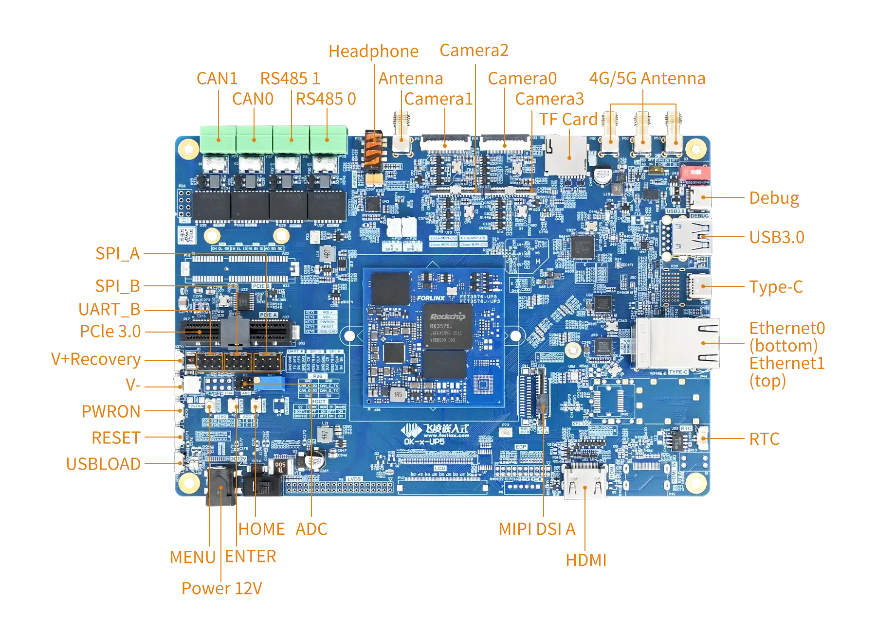
| MIPI CSI | 4 | 1 x MIPI DPHY V2.0 4-lane interface, supporting up to 4.5 Gbps per lane; connected via a 26-pin FPC socket, with the OV13850 camera mounted by default; 3 x MIPI DPHY V1.2 2-lane interfaces, supporting up to 2.5 Gbps per lane; brought out via three 26-pin FPC sockets; pre-mounted with an OV5645 camera by default; |
| MIPI DSI | 1 | Each MIPI interface supports 4 lanes of output, with a maximum resolution of 2560 x 1600@60Hz; Compatible with Forlinx 7-inch MIPI display, with a resolution of 1024 x 600@30fps; |
| HDMI TX | 1 | Led out via a standard HDMI connector; supports up to 7680x4320@60Hz. |
| USB3.2 Gen1 | 1 | Routed through a Type-C connector; |
| USB3.0 Host | 1 | Routed through a Type-A USB connector; |
| PCIe2.1 | 1 | Led out x 4 slot; · Supports 5Gbps speed; |
| Ethernet | 2 | Connected via a single dual-layer RJ45 socket; · Supports data transfer rates of 10/100/1000 Mbps; |
| TF Card | 1 | TF card is available, rate up to 150MHz,support SDR104 mode; |
| Audio | 1 | On-board codec chip, supporting functions such as headphone output, microphone input and speaker output; |
| RS485 | 2 | 2 x RS485 CAN bus routed out through RS485 transceiver; |
| CAN | 2 | Connect one CAN bus via the CANFD transceiver; |
| UART | 1 | Led out via 2.54 mm pitch;Up to 4Mbps baud rate; |
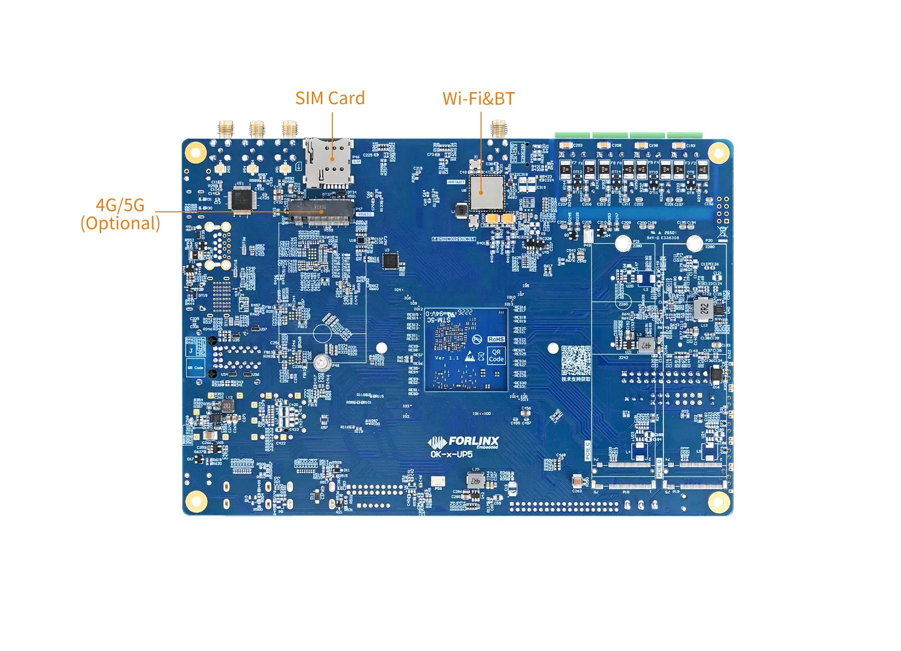
| 4G/5G | 1 | Supports M.2 packaged 4G/5G modules; |
| WIFI&BT | 1 | On-board Wi-Fi and Bluetooth module; an external Wi-Fi antenna must be connected |
| ADC | 3 | Led out via a PH2.0 socket; · 12-bit resolution and a sampling rate of up to 1 MS/s; |
| RTC | 1 | Onboard RTC chip and battery socket; |
| SPI | 2 | Routed through a 2.54mm pitch connector; |
| FAN | 1 | On-board fan connector; |
Note*: The parameters in the table are the theoretical values of hardware design or CPU.
▊ Accessories
Please click here to get more information about the supported modules and accessories.
▊ Documentation
Reference Manuals
Hardware Related
Product Datasheet
User Guide
Carrier Board Schematic
Carrier Board PCB
SoM Pinmux
Software & BSP
OS Image
Testing Demo
Source Code
Manual
Request a Quote
Fill out the form below for volume pricing or technical specifications. We'll get back to you within 24 hours.
▊ Ordering Information
1. Online Channels: We have an online store on Alibaba and DigiKey. Please contact us for details.
2. Direct Inquiry: For bulk orders, please email our sales team at [email protected].
3. Payment Method: Standard terms: 100% T/T (Telegraphic Transfer) in advance.
1. Dispatch Method: Orders are shipped via international express upon receipt of payment.
2. Lead Time: 5 working days for samples; 6 weeks for bulk orders.
3. Shipping Policy: Shipping and handling fees are the responsibility of the purchaser.
▊ Forlinx Recommended Products
Architecture: 4x Cortex-A72 + 4x Cortex-A53
Frequency: [email protected][email protected]
RAM: 8GB LPDDR4,2GB/4GB LPDDR4
ROM: 16GB eMMC,32GB/64GB eMMC
Architecture: 4x Cortex-A76+4x Cortex-A55
Frequency: [email protected]/1.6GHz, [email protected]/1.3GHz
RAM: 4GB/8GB/16GB/32GB LPDDR4
ROM: 32GB/64GB/128GB eMMC