


Qualcomm QCS8275AA Single Board Computer - Forlinx OK8275AA-C 8-Core Edge AI Development Kit
The OK8275AA-C development board is a production-ready evaluation platform built around the FET8275AA-C SoM and the Qualcomm Dragonwing QCS8275AA processor. With an 8-core Kryo CPU, a 40 TOPS NPU and a dedicated 4-core real-time subsystem already validated on the module, the board lets you evaluate edge AI, machine vision and industrial control workloads without designing a carrier board first.
The carrier board routes out the interfaces that matter for rapid prototyping: dual Ethernet (1x 1GbE + 1x 2.5GbE), 4x isolated CAN-FD, 2x isolated RS485, three MIPI CSI camera connectors pre-matched to IMX577 modules, a MIPI DSI display connector for the 7-inch 1024x600 panel, and DP 1.4 for standard monitors. An M.2 Key-E slot carries Wi-Fi & Bluetooth, while a second M.2 slot takes a 4G/5G module.
Storage and expansion are equally covered: 256GB UFS 3.1 on the module, a TF card slot sharing the SD interface with eMMC, a PCIe x1 slot, two USB 3.0 ports and one USB 2.0 host port. Rated for -40°C to +85°C operation with a DC 24V input and an onboard fan header, the OK8275AA-C is built to move from bench evaluation to pilot deployment with a single image.
Built Around the FET8275AA-C SoM
Everything that makes the module attractive—8-core Kryo compute, Adreno 623 graphics, 40 TOPS NPU, 12GB LPDDR5 and 256GB UFS 3.1—arrives on the board already integrated, powered and cooled. You evaluate the exact silicon you will ship, then move the same SoM onto your own carrier board when the design is proven.
Industrial I/O Ready to Wire
Four CAN-FD ports and two RS485 ports leave the board with isolation and protection already fitted, so drives, PLCs and battery systems can be connected on day one. A 40-pin expansion header and FPC connectors expose the remaining MD and RTSS GPIOs.
Triple-Camera Vision Pipeline
Three MIPI CSI connectors are routed to FPC and pre-matched to IMX577 modules, supporting D-PHY and C-PHY configurations up to 93 Gbps aggregate. Combined with the 40 TOPS NPU, the board runs multi-camera inspection, pose estimation and defect detection locally.
Dual Ethernet with TSN
1GbE + 2.5GbE
One RGMII port at 1GbE and one SGMII port at 2.5GbE give the board a separate real-time and IT-side network path. TSN support on the SoM keeps cyclic control traffic deterministic while camera and AI data travel over the second link.
M.2 Expansion & Display Outputs
An M.2 Key-E slot hosts the Wi-Fi & Bluetooth module, a second M.2 slot accepts 4G/5G, and a PCIe x1 slot is available for accelerators or frame grabbers. Outputs include MIPI DSI for the 7-inch panel and DP 1.4 for a standard monitor.
Industrial-Grade by Default
Rated -40°C to +85°C with a DC 24V input, onboard RTC with battery holder, JTAG header for all cores and a fan connector for sustained loads. USB Type-C handles system flashing, so a single cable brings a fresh board to a working Linux image.
▊ FET8275AA-C SoM Parameters
| FET8275AA-C System On Module Basic Parameters | |
|---|---|
| Processor | Qualcomm QCS8275AA |
| ARM:2x Kryo Gold Prime @2.35GHz + 2x Kryo Gold @2.1GHz + 4x Kryo Silver @1.95GHz | |
| NPU:40 INT8 TOPS (Dense) | |
| GPU:Adreno 623 GPU | |
| VPU:Adreno 623 VPU | |
| RAM | 12GB LPDDR5 |
| ROM | 256GB UFS 3.1 |
| Operating Temperature | -40°C ~ +85°C |
| Operating Voltage | DC 24V |
| Connection | Mirror Mezz 699-pin board-to-board connector |
| OS | Linux 6.18.44 |
| Flashing | USB Type-C |
| TF card | |
▊ SoM Function Parameters
| FET8275AA-C System On Module Function Parameters | ||
|---|---|---|
| Function | QTY | Spec. |
| MIPI DSI | 1 | 1 x MIPI DSI with VESA DSC v1.2 support; |
| D-PHY v1.2: 2.5 Gbps/lane on four lanes per port, 10 Gbps total; | ||
| C-PHY v1.1: 5.7 Gbps/trio on three trios per port, 17 Gbps total. | ||
| DP 1.4 | 1 | 1 x DisplayPort v1.4, 8.1 Gbps per lane, 32.4 Gbps aggregate port bandwidth. |
| MIPI CSI | 3 | 3 x MIPI CSI configurable as D-PHY or C-PHY mode; |
| D-PHY v1.2: 2.5 Gbps/lane, 4 lanes per port, 10 Gbps per port, up to 30 Gbps total; each 4-lane port can be split into 1-lane + 2-lane or 1-lane + 1-lane combinations; | ||
| C-PHY v1.2: 10.2 Gbps/trio, 3 trios per port, 31 Gbps per port, up to 93 Gbps total; each 3-trio port can be split into 1-trio + 2-trio, or three independent 1-trio ports. | ||
| I2S | Up to 8 | LS-I2S: 5 dedicated low-speed I2S, 2 multiplexed with high-speed I2S, plus 1 dedicated high-speed I2S reconfigurable as low-speed (up to 8 LS-I2S in total, max clock 24.576 MHz); |
| HS-I2S: up to 3, of which 2 are multiplexed with LS-I2S and can be configured as LS-I2S when needed (max clock 73.728 MHz). | ||
| PCIe | 2 | 1 x 2-lane PCIe Gen4: PCIe0 (RC + EP); |
| 1 x 4-lane PCIe Gen4: PCIe1 (RC + EP). | ||
| USB | 2 | 1 x USB 3.1 Gen2 – USB0 (HS + SS, supports device and host modes); |
| 1 x USB 2.0 – USB2 (HS, supports device and host modes). | ||
| eMMC | 1 | 1 x 8-bit eMMC 5.1 interface, max clock frequency 192 MHz. |
| RGMII | 1 | 1 x RGMII interface (RTSS domain). |
| SGMII | 1 | 1 x SGMII interface, up to 2.5GbE. |
| CAN-FD | Up to 4 | 4 x CAN-FD (RTSS domain). |
| QUP | 21 | MD domain: 16 QUP serial engines — UART (64B FIFO), all QUP SEs configurable as UART; |
| MD domain: HS UART (128B FIFO), QUP0_SE_2/3, QUP1_SE_2/3 configurable as HS UART; | ||
| MD domain: I2C master, all QUP SEs configurable as I2C; | ||
| MD domain: I3C, QUP0_SE_0/1, QUP1_SE_0/1 configurable as I3C; | ||
| MD domain: SPI master, all QUP SEs except QUP0_SE_7 and QUP1_SE_3 configurable as SPI master; | ||
| MD domain: SPI slave, QUP0_SE_4/5, QUP1_SE_4/5 configurable as SPI slave; | ||
| RTSS domain: 5 QUP serial engines — UART (64B FIFO), all QUP SEs configurable as UART; | ||
| RTSS domain: HS UART (128B FIFO), QUP0_SE_2/3 configurable as HS UART; | ||
| RTSS domain: I2C master, all QUP SEs configurable as I2C; | ||
| RTSS domain: SPI master, all QUP SEs configurable as SPI master; | ||
| RTSS domain: SPI slave, QUP0_SE_0/1 configurable as SPI slave. | ||
| QSPI | 1 | 1 x QSPI (up to 100 MHz). |
| GPIO (MD domain) | Up to 133 | Main domain supports 133 GPIOs (GPIO_0 to GPIO_132). |
| GPIO (RTSS domain) | Up to 68 | RTSS domain supports 68 GPIOs (RTSS_IO_0 to RTSS_IO_67). |
Note*: The parameters listed above are based on hardware design or theoretical CPU limits. Interfaces may be multiplexed; numbers represent maximum theoretical availability.
▊ Development Board Function Parameters
| Development Board Function Parameters | ||
|---|---|---|
| Function | QTY | Spec. |
| MIPI DSI | 1 | Routed via FPC connector, default matching Forlinx 7-inch MIPI display at 1024x600@30fps. |
| DP 1.4 | 1 | Routed via DP port, default compatible with standard DP monitors. |
| MIPI CSI | 3 | Routed via 3 FPC connectors, default matching IMX577 camera modules. |
| Audio | 2 | 1 x I2S with MAX98357AETE+ amplifier, supporting 4Ω 1.3W / 8Ω 0.8W speakers; |
| 1 x I2S with codec chip, supporting speaker, headphone output and MIC input (TBD). | ||
| Type-C OTG | 1 | Type-C and Type-A switched via analog switch (S5 controls direction: OFF for Type-C, ON for Type-A); |
| System flashing uses the Type-C port. | ||
| USB 3.0 | 2 | Type-C and Type-A switched via analog switch (S5 controls direction: OFF for Type-C, ON for Type-A); |
| Type-A and 4G/5G module are onboard HUB expansion interfaces. | ||
| USB 2.0 | 1 | 1 x USB 2.0 Type-A port. |
| 4G/5G | 1 | Supports M.2 4G/5G module. |
| M.2 | 1 | 1 x M.2 KEY-E interface, 2-lane, default matching Wi-Fi & BT module. |
| PCIe | 1 | 1 x PCIe x1 slot (4-lane interface). |
| TF Card | 1 | Shares the SD interface, selected via 0Ω resistor. |
| eMMC | 1 | Shares the SD interface, selected via 0Ω resistor. |
| Ethernet | 2 | 1 x Ethernet port up to 1 GbE; 1 x Ethernet port up to 2.5GbE. |
| RS485 | 2 | 2 x RS485 ports with isolation and protection. |
| CAN-FD | 4 | 4 x CAN-FD ports with isolation and protection. |
| RTC | 1 | I2C interface, onboard RTC chip with button battery holder. |
| JTAG | 1 | JTAG debugging via pin header. |
| FAN | 1 | Fan connector for SoM cooling. |
| GPIO | n | Remaining MD_GPIO and RTSS_GPIO routed via FPC and pin headers for expansion. |
Note*: The parameters listed above are based on hardware design or theoretical CPU limits. Interfaces may be multiplexed; numbers represent maximum theoretical availability.
▊ Accessories
Please click here to get more information about the supported modules and accessories.
▊ Documentation
Reference Manuals
Hardware Documents
Product Datasheet
User Guide
SoM Pinmux
Carrier Board Schematic
Carrier Board PCB
Software Documents
Linux BSP User Guide
Driver Source Code
Driver Porting Guide
Flashing Guide (USB Type-C)
Request a Quote
Fill out the form below for volume pricing or technical specifications. We'll get back to you within 24 hours.
▊ Ordering Information
1. Online Channels: We have an online store on Alibaba and DigiKey. Please contact us for details.
2. Direct Inquiry: For bulk orders, please email our sales team at [email protected].
3. Payment Method: Standard terms: 100% T/T (Telegraphic Transfer) in advance.
1. Dispatch Method: Orders are shipped via international express upon receipt of payment.
2. Lead Time: 5 working days for samples; 6 weeks for bulk orders.
3. Shipping Policy: Shipping and handling fees are the responsibility of the purchaser.
▊ Forlinx Recommended Products
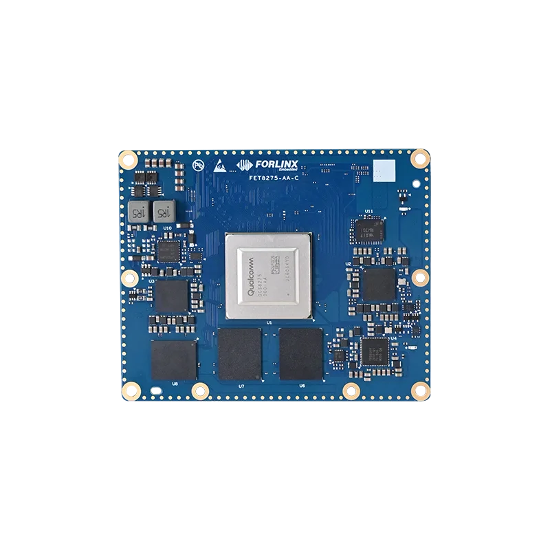
Architecture: 2x Kryo Gold Prime + 2x Kryo Gold + 4x Kryo Silver
Frequency: 2.35GHz + 2.1GHz + 1.95GHz
RAM: 12GB LPDDR5
ROM: 256GB UFS 3.1